Thank you for sharing
🙂 S3tup
and for the guys with technical skill and understanding, here a testimonie about output stage:
http://www.diyaudio.com/forums/digital-source/227677-using-ad844-i-v-74.html#post3877011
🙂 S3tup
and for the guys with technical skill and understanding, here a testimonie about output stage:
http://www.diyaudio.com/forums/digital-source/227677-using-ad844-i-v-74.html#post3877011
I have built and listened to many output stages, including Lampizator's output stage,
(which essentially is an Audio Note-inspired output stage).
Despite its technical shortcomings and poor implementation, it sounded outstanding.
I don't use it anymore, but it was imho an excellent output stage.
Hi, I'm curious to know what D/A chip you used to evaluate its subjective performance. IIRC 100 ohm I/V and output from the plate of the lower tube has it with quite some issues with tda1541A, especially on the input side.
If its still available, perhaps you could revisit the build with <47R I/V and report back.
Don't know why you dismiss OP861 so quickly, it has Zin of <10ohm and operates without feedback. AD844 was the predecessor and was well received, as was the OP861 when it was released commercially and reviewed. In fact, you couldn't have possibly tried the OP861 as prescribed unless you purchased the commercial product because the complete circuit (as in - something you can build) was never released. That probably violates one of your design criteria points ie. Not knowing what you're talking about 🙂
Having the commercial implementation of OP861 here, and also having built the Lamp output as prescribed I can tell you with absolutely no uncertainty that the Lamp cct loses out big time. Moving forward, Thorstens 6922 cct is better than both (and 6072A also if you can live with the lower Ip in dealing with driving more complex loads ie. transformer inputs at the following stage etc.)
Hey Eldam.. you crack me up.. that thing about Star Wars and you being Chewbakka (sp?) was the most colourful and meaningful thing I've seen here.. nice to know there are real (like actual ones) people out there. 🙂 🙂 🙂
Hugs and kisses, cheeks only - and they be the ones on your face.
Shane
Last edited:
Ceglar said:IIRC 100 ohm I/V and output from the plate of the lower tube has it with quite some issues with tda1541A, especially on the input side.
If its still available, perhaps you could revisit the build with <47R I/V and report back.
Please see my earlier comments:
http://www.diyaudio.com/forums/digi...any-good-tda1541a-dac-kit-65.html#post3873029
http://www.diyaudio.com/forums/digi...any-good-tda1541a-dac-kit-66.html#post3873718
Don't know why you dismiss OP861 so quickly, it has Zin of <10ohm and operates without feedback.
There is no component called OP861
That probably violates one of your design criteria points ie. Not knowing what you're talking about 🙂
Does this comment give you gratification?
Having the commercial implementation of OP861 here, and also having built the Lamp output as prescribed I can tell you with absolutely no uncertainty that the Lamp cct loses out big time.
Fine, go with your choice. I respect your opinion.
Good luck all.
...
Don't know why you dismiss OP861 so quickly, it has Zin of <10ohm and operates without feedback. AD844 was the predecessor and was well received, as was the OP861 when it was released commercially and reviewed. In fact, you couldn't have possibly tried the OP861 as prescribed unless you purchased the commercial product because the complete circuit (as in - something you can build) was never released. That probably violates one of your design criteria points ie. Not knowing what you're talking about 🙂
...
I don't know if Shane's comment was intended as an insult. It's ambiguous (and a wink smiley would have made it more clear) but it could be he's saying that one your design criteria is that you do know what you're talking about (you have a deep and technical understanding of the electronics you design)
OPA861
http://www.diyaudio.com/forums/digital-source/240987-opa861-i-v.html
...but it could be he's saying that ne your design criteria is that you do know what you're talking about...
OPA861
Thank you Audiolapdance for your comments.
I am sorry to disappoint you all, but I am absolutely not an expert.
The more I have researched, the more I realize how little I know.
OPA861 is not a single transistor in a Plastic Package.
It contains many many many semiconductors, etched together on a Silicon Substrate.
Remember:
IC-Manufacturers have Design Objectives that are quite
dissimilar to what Hi Fidelity Circuit Design aims to satisfy.
Fairly good results can be obtained with IC's.
Once again, I am not an expert.
Neither do I have the energy to inform fellow Audiophiles about my past to gain credentials.
If any one wants to use IC's - fine, do it.
Just a thought:
There are no IC's in the Analog Signal Path of the AMR CD-77.
Is Mr. Thorsten Loesch delusional?
Can there be a possible reason as to why he uses no IC's in the Analog Stage of the CD-77? ...I don't know.
Good luck to u all.
Last edited:
By definition a current output DAC would see an impedance of 0 ohm at its output.
So, if one wouldn't use an OPAMP, IMHO, the best choices are: grounded gate, grounded grid, common base (not in order of preference).
Obviously they don't provide 0 ohm input impedance, but anyway very low.
So, if one wouldn't use an OPAMP, IMHO, the best choices are: grounded gate, grounded grid, common base (not in order of preference).
Obviously they don't provide 0 ohm input impedance, but anyway very low.
Allexis, you're very modest. I collect good info from trusted sources but only have a grasp on the technicals. You have a solid grip on the technicals.
...
Yes the OPA861 has many parts inside but it has good performance and works well as a common base I/V (and buffer):
(image removed due to copyright concerns)
Tubes frustrate me a bit in that they need warmup and deteriorate over time, so ... a solid state solution that provided almost the performance of tubes... That said, I have T's UTS (Universal Stereo Tube Output Stage) on my crappy 1541 S1 and:


Mmmm, sweet! 😉
...
Yes the OPA861 has many parts inside but it has good performance and works well as a common base I/V (and buffer):
(image removed due to copyright concerns)
Tubes frustrate me a bit in that they need warmup and deteriorate over time, so ... a solid state solution that provided almost the performance of tubes... That said, I have T's UTS (Universal Stereo Tube Output Stage) on my crappy 1541 S1 and:
Mmmm, sweet! 😉
Last edited by a moderator:
...Tubes frustrate me a bit in that they need warmup and deteriorate over time, so ...
Unfortunately they do.
Yet they were the preferred choice of the foremost authority on TDA1541 chip, when
deciding to create what according to MANY, is:
the best digital sound machine on the planet.
Do we still need to insist on using IC's?
...OPA861 has many parts inside but it has good performance and works well as a common base I/V (and buffer)...
Yes, so would a NE553x.
Good luck to u all.
Last edited:
...
the best digital sound machine on the planet.
...
Yes, yes I know ...
However, I'm not among those on the planet well off enough to get one so ...
any idea of the circuit?
Fast Audio review:
Fast Audio
Thomas Fast
Brählesgasse 21
70372 Stuttgart
www.fastaudio.com
View attachment Image%20HiFi%20Review%20AMR%20CD-77.pdf
Last edited:
Interesting Review Audiolapdance.
I had not seen it before, interesting.
Thanx for sharing..
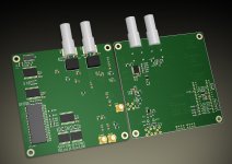
The digi interface PCB is 50% complete. SAA7220 dropped as it was counter-productive. It was a bad performing DF anyway.
No PS section yet 🙁
Wow, looks good dude!
Here I am drooling over tubes and you're actually getting some work done! Keep it up!
Does anyone have any ok test gear that could help s3tup with testing and possible debugging of a rev 1 board?
Cheers all,
Jeff
Help - you mean donate the equipment to me? 🙂 I'd be happy with a E5052B plus some okayish scope of >>2GHz BW... 🙂
No, i don't need any equipment for the rev1 board, PS section works, it's time for casework + output stage.
No, i don't need any equipment for the rev1 board, PS section works, it's time for casework + output stage.
No, I meant that you could send a beta PCB to someone who has good equipment ... but now I realize that's over stepping the bounds. I allowed my eagerness to override my politeness ... gasp, and I'm Canadian! 
...
I sincerely apologize (ok, now I've redeemed some of my Canadianness! Whew!)
---------------------------------------------
I recall T saying the the SAA7220 is very noisy and needs superlative PS bypassing and GNDing to not muck up a design ...
T on internal functioning:
"...these implementation details are questionable and I would not use the SAA7220 in any new design."
T on noise and a crappy PCB:
"Okay, the SAA7220 is a MASSIVE noise generator. It's decoupling matches that of the rest of the digital section, that is it has for all intents grassmudhorse all decoupling. The single ferrite bead between the SAA7220 PSU will help, but likely not remotely enough, especially as the "far side" of it is not decoupled...
Just poking a 'scope around the PSU pins on this PCB will be feast for the eyes, I'd predict noise levels in the 100's of mV around the filter and probably no better for the rest."

...
I sincerely apologize (ok, now I've redeemed some of my Canadianness!
Whew!) ---------------------------------------------
I recall T saying the the SAA7220 is very noisy and needs superlative PS bypassing and GNDing to not muck up a design ...
T on internal functioning:
"...these implementation details are questionable and I would not use the SAA7220 in any new design."
T on noise and a crappy PCB:
"Okay, the SAA7220 is a MASSIVE noise generator. It's decoupling matches that of the rest of the digital section, that is it has for all intents grassmudhorse all decoupling. The single ferrite bead between the SAA7220 PSU will help, but likely not remotely enough, especially as the "far side" of it is not decoupled...
Just poking a 'scope around the PSU pins on this PCB will be feast for the eyes, I'd predict noise levels in the 100's of mV around the filter and probably no better for the rest."
Last edited:
Yep, the PS pins arrangement of SAA7220 looks so 70's. Fortunately i've already dropped it. SAA7220 has 180mA(!!!!!!) supply current, what the heck?!. CXD is qouted for 100mA absolute maximum, when DF1700 is just 50mA...
Another reason of why people favor NOS desings over the "classic" 7220 🙂
The CXD1244 and DF1700 have much better PS pin locations - right next to each other, in the middle of the IC. As close as anyone could hope for.
I plan to throw paralel regulators all over the digital section as i don't want the currents from nasty logic ICs to flow all over the place. At least the DF and WM's PS. Other ICs shouldn't be so angry for the PS as they have no processing inside and don't need to charge much capacitance on their outputs.
That's the reason of separated digital PCB. Clock section is tad compromise, so i threw EXT connector to be able to override PCB's clock circuit with external one. Anyway, the onboard clock should be cased separately due to different EMC and thermal factors. I'll need to measure it one day, and i'm already getting ready for that: half-built software tool for displaying long FFTs in a manner the good old SSA do:
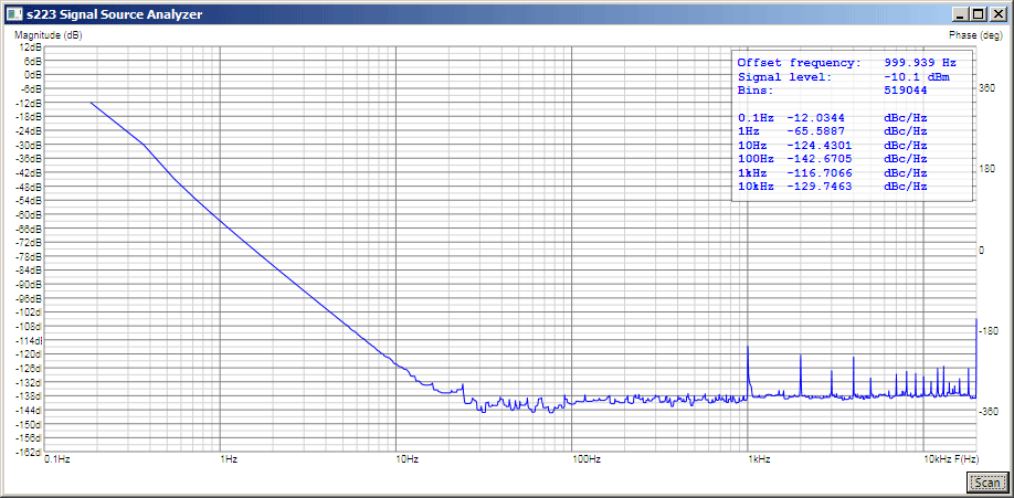
^^^ It's not a clock, just a FFT of loopback of my soundcard. Sine wave centered at 1khz, the picture shows the spurs near the 1khz tone. No apparrent jitter as the sampling and playback clocks are the same one, thus no clock difference possible.
Huh, maybe there is some jitter, dunno 🙂
Another reason of why people favor NOS desings over the "classic" 7220 🙂
The CXD1244 and DF1700 have much better PS pin locations - right next to each other, in the middle of the IC. As close as anyone could hope for.
I plan to throw paralel regulators all over the digital section as i don't want the currents from nasty logic ICs to flow all over the place. At least the DF and WM's PS. Other ICs shouldn't be so angry for the PS as they have no processing inside and don't need to charge much capacitance on their outputs.
That's the reason of separated digital PCB. Clock section is tad compromise, so i threw EXT connector to be able to override PCB's clock circuit with external one. Anyway, the onboard clock should be cased separately due to different EMC and thermal factors. I'll need to measure it one day, and i'm already getting ready for that: half-built software tool for displaying long FFTs in a manner the good old SSA do:
^^^ It's not a clock, just a FFT of loopback of my soundcard. Sine wave centered at 1khz, the picture shows the spurs near the 1khz tone. No apparrent jitter as the sampling and playback clocks are the same one, thus no clock difference possible.
Huh, maybe there is some jitter, dunno 🙂
Last edited:
If the 861 outputstage or 3 stacked AD844 per canal are not enough for the SQ (!) , we may come close to the Gomez . The Gomez in the AMR-77 is not very complicated : big chock for filtering the wall curent, it seems not to be on the photographs a tube rectifier circuit (but I'm not a specialist, good tubes (but NOS... problem), the output is a simple MKP cap dc blocker.
But this not very universal if the project suceess! Tubes DIY can be deadly !
Gomez Vs XPP Amplifier
some kits and bare (or not pcbs)
Aikido 5687 Stereo All-in-One PCB and Kit
The All-in-One Line-Stage/Head-Phone Amplifier
we know by T. himself than the best I/v resistor are the Rhopoint (wirewound Z foil non inductive: avaliable at Mouser).
T. like for the first stage the Siemens 3A... don't remenber exactly the ref than Andrea Ciuffoli use everywhere in him input stages (Amp and DAC).
But the day where we will be at this point....
if a pcb need really to be tested about RF and Layout efficienty (at the end of the process) , there is a fellow with great RF knowledge ( this is him job). But he is very busy. I think he can print the pcb easily if the data files and do some short checks if the data files could be send. I needed & if he will agree with such sharing, I can send & give him one TDA1541 as I have four.... This is my neighbour as he is a britanic. His fellow name is: Marce. Audiolapdance if you would manage a gentle invitation by pm to him with a not Chewbacka english you know that one of my TDA could be given to him as a symbol to him help...
just 2 cents... all I can is giving one TDA1541 DAC chip to him to participate.
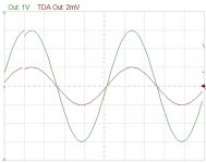
This is the simulation of the tube output stage I'm building for the TDA. Tube's models are generated from real curves extracted with a curve tracer. No IV resistor is needed. No feedback.
The green plot is the output signal of the stage, around 3V p-p.
The brown plot is the signal developed at the TDA's output, around 2mV p-p. So the DAC see 1 ohm impedance.
The simulated harmonic distorsion is less than 0.001%.
Is the 300B really the Queen?
The green plot is the output signal of the stage, around 3V p-p.
The brown plot is the signal developed at the TDA's output, around 2mV p-p. So the DAC see 1 ohm impedance.
The simulated harmonic distorsion is less than 0.001%.
Is the 300B really the Queen?
Attachments
Last edited:
This is the simulation of the tube output stage I'm building for the TDA. Tube's models are generated from real curves extracted with a curve tracer. No IV resistor is needed. No feedback.
The green plot is the output signal of the stage, around 3V p-p.
The brown plot is the signal developed at the TDA's output, around 2mV p-p. So the DAC see 1 ohm impedance.
The simulated harmonic distorsion is less than 0.001%.
Is the 300B really the Queen?
Sounds interesting andrea_mori, care to share any more details?
Excellent Work
s3tup + andrea_mori = Very good job. Your inputs are most welcome.
AudioLapDance + Eldam = Excellent work. I think the project is coming along nicely.
BTW, I found this interesting quote from --> The One & Only Mr. ECDesigns:
This is exactly according to my own exhaustive and prolonged research into the subject.
If the OPA861-Based Analog Stage so clearly outperformed
the Totempole GK Amp (Audio Note Style Analog Stage) according to Mr. Ceglar, then u did something wrong.
(BTW: I would much recommend the MAX435 than the OPA86x if any one wishes to use ota's.
MAX was more fluent, more liquid with much better bass...)
Still if anyone firmly believes in the sonic superiority of Integrated Circuits, by all means, I respect your opinion.
Good luck to u all.
s3tup + andrea_mori = Very good job. Your inputs are most welcome.
AudioLapDance + Eldam = Excellent work. I think the project is coming along nicely.
BTW, I found this interesting quote from --> The One & Only Mr. ECDesigns:
... test with differential passive I/V and a modified TUBEDIF module showed how well passive I/V can perform.
...I thought tubes were obsolete relics of the past, and I had full confidence in modern technology (for High-End audio applications).
Now, after almost 2 years of designing, tweaking and testing, I have to conclude that it's the other way around.
Even the very best modern audio Op-amps can't even come anywhere near the performance of a low distortion tube amplifier.
http://www.diyaudio.com/forums/digi...e-nos-dac-using-tda1541a-196.html#post1482362
This is exactly according to my own exhaustive and prolonged research into the subject.
If the OPA861-Based Analog Stage so clearly outperformed
the Totempole GK Amp (Audio Note Style Analog Stage) according to Mr. Ceglar, then u did something wrong.
(BTW: I would much recommend the MAX435 than the OPA86x if any one wishes to use ota's.
MAX was more fluent, more liquid with much better bass...)
Still if anyone firmly believes in the sonic superiority of Integrated Circuits, by all means, I respect your opinion.
Good luck to u all.
Last edited:
…
If the OPA861-Based Analog Stage so clearly outperformed the Totempole GK Amp (Audio Note Style Analog Stage) according to Mr. Ceglar, then u did something wrong.
…
That's one possibility, that he did something wrong.
Yet, there is another possibility. I found out the different people have entirely different taste and preferences, concerning sound. Also, what may sound good on one setup may sound bad on another one. Which is why there is never going to be agreement between all people.
- Status
- Not open for further replies.
- Home
- Source & Line
- Digital Line Level
- Any good TDA1541A DAC kit?