hihopes said:I have downloaded the datasheet for irf9610 from International Rectifier, but it doesn't show the pinout - just says it is a TO220AB package. As far as I can find out, this seems to have a pinout of G,D,S (looking from the front). Can anyone confirm this? I am drawing up a PCB and obviously need to get this right. I can post a jpg of the PCB if anyone is interested, or would like to give feedback on it.
This is from a Samsung Electronics datasheet.
Attachments
PCB
Hello Hihopes,
Are you planning the PCB for two IRF9610 or for the, at least simmed better, one IRF9610 and BJT(MJ350) for the lower device?
I am drawing up a PCB
Hello Hihopes,
Are you planning the PCB for two IRF9610 or for the, at least simmed better, one IRF9610 and BJT(MJ350) for the lower device?
Thanks - G,D,S it is.
The first PCB will be for the 2 mosfets. My past experience tells me that mosfets tend to be quieter, or at least more benign-sounding than BJT's. (J-fets are my real preference - after valves of course)
This will not be an Eagle or other commercial effort. I am doing it in Coreldraw. I print it out on label paper, stick the paper on to the top side of the pcb sheet and use it for a drilling guide. Then I connect the drilled holes as required with a black felt-tip marker and etch the board. Primitive perhaps, but cheap and effective. (I have built up a library of parts at exact scale in Coreldraw over the last few months.)
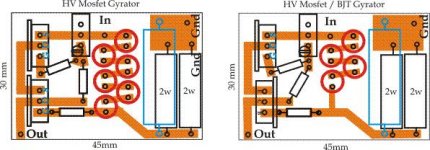
If you print them out at the measurements shown next to the boards, they will be exactly to scale. All resistors are 1/4 w except those shown as 2w. There is an optional larger resistor instead of the parallel 2w's. It is shown in blue, but please note that since I did not have one to measure, I took a bit of a guess at the size of it.
Why MOSFETs? The obvious solution should be to go for a PJF or MOSFET at the top followed by a PNP.
Even if MOS are easier to handle they are not the obvious choice due to their extreme capacitances. This also shows as they give a more restricted bandwith than with BJT.
Even if MOS are easier to handle they are not the obvious choice due to their extreme capacitances. This also shows as they give a more restricted bandwith than with BJT.
hihopes said:If you print them out at the measurements shown next to the boards, they will be exactly to scale. All resistors are 1/4 w except those shown as 2w. There is an optional larger resistor instead of the parallel 2w's. It is shown in blue, but please note that since I did not have one to measure, I took a bit of a guess at the size of it.
Did you think of space for sinking the lower part? There are voltage and current situations that it will need sinking.
hihopes said:I will try to attach the PCB drawings.
You forgot to put a capacitor on the PCB.
In the first place, why make PCBs for a prototype? Even if it, as in this case, seems very promising. As Salas indicates listenning test should be done.
I am eager to try the "CVS" as driver load in a DC coupled SE with trioded E280F and 6B4G.
In this case the "CVS" could be used to fine tune bias for the output tube.
Will be back with a full schematic.
I am eager to try the "CVS" as driver load in a DC coupled SE with trioded E280F and 6B4G.
In this case the "CVS" could be used to fine tune bias for the output tube.
Will be back with a full schematic.
Forgot the capacitor! I feel really stupid now. Back to the drawing board. Of course, since there are so many different options for capacitors, the board will have to be MUCH bigger. Any other problems?
Revintage, if you look more closely, you will see that the board on the right is a for a Pmos + MJE350.
Heat-sinking for the 2-mosfet version , no problem, but since the BJT is turned around the other way, that board as it is would not allow for a heatsink.
Why a PCB for a prototype? Why not? I am tired of messing about with stripboard, and since I make the PCB's myself, there is no cost involved. Besides, I fully intend to use this design. I am convinced that it is better than a resistor or a CCS.
Revintage, if you look more closely, you will see that the board on the right is a for a Pmos + MJE350.
Sorry, didn t look close enough
 !
!Also make enough room for the cap as it in some cases needs to be at least 22u, plastic type.
And if you are stuck to make the board for prototyping, make place for alternative MOSFET/BJT on the same card.
On the downside of this circuit is heavy phase-errors. Any suggestions Wavebourn? With 10mA 300V/150V IRF9610/MJE350 I get indications of over 20degrees at 20Hz.
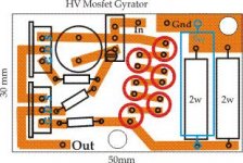
First edit - added place for 10mm 'lytic with 5mm leg spacing. Also added 2 mounting holes. By stretching the board slightly to the left, another can be added top left, or a heatsink can support the left side of the board. Serious redesigning will be required for plastic caps, or they will have to be mounted next to the board and connected with wires.
Any other comments before I redo the BJT version?
Any other comments before I redo the BJT version?
Attachments
I see there is very little space between the cap and the upper mosfet. Does the upper mosfet get hot?
Do you think it is a good idea if I start selling kits?
I can order PCBs, parts, and offer BCBS, kits with parts, assembled gyrators...
However, if an interest exists.
I can order PCBs, parts, and offer BCBS, kits with parts, assembled gyrators...
However, if an interest exists.
You mentioned some time ago that the PSRR is rather poor and could be much improved if the cct was referenced to ground. I would suggest that if you are going to go to all the trouble of printing boards and offering kits, it might be worth the effort to redesign it along those lines and thus offer a more optimal product. Just my opinion.
I ran into a dude this weekend who wants to drive electrostatic
speakers with 845's . I suggested he find this thread and consider
gyrators for his plate loads, rather than his originally planned 8K
resistors. That both front and back of his statics might idle exactly
660V, with no special worries for DC matching...
However, his B+ is likely to be 1100V. So some rethink may be in
order how to keep such gyrators from blowing up. Are any P-type
devices able to handle it? How might one do this with N-Channel
IGBT's? And rather than simply gyrate, I'd like to investigate if its
also possible to have anti- triode behavior above DC.
hihopes said:You mentioned some time ago that the PSRR is rather poor and could be much improved if the cct was referenced to ground. I would suggest that if you are going to go to all the trouble of printing boards and offering kits, it might be worth the effort to redesign it along those lines and thus offer a more optimal product. Just my opinion.
I can add a voltage regulator on top.
- Status
- Not open for further replies.
- Home
- Amplifiers
- Tubes / Valves
- Anti-Triode SEPP, how to do best?