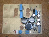
Second channel completed. I'll wait till tomorrow to verify it before powering it up.
I may build a copy before starting on the chassis.
Nice!
I use a usb connection on the TV to turn on the amp. Just find a 5 volt at less than 1/2 amp relay.
mr2racer, I hope your dining room table has fewer holes and gouges it than my workbench 😉
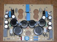
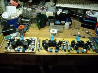
All three boards are completed and I'm testing them and adjusting the bias pots.
So far the first board had both channels come up within expected tolerances. I can adjust the bias to allow either Triode (3.5W) or UL (5.6W) mode at the flip of a switch without changing the bias, although Triode mode runs a bit hotter.
Triode mode I'm dissipating 17.8W, and UL mode I'm dissipating 15.48W. This is a sweep tube rated for 14W. based on previous tests for maximum dissipation before red-plating, I feel that I'm running it conservatively.
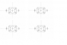
I think I've come up with an easy way to make IEC Connector cutouts.
I print off this template at 100% size, cut out one section, spray it with #77 contact glue, affix the template to the chassis and drill out as indicated, then use a nibbler and finish with a file.
I print off this template at 100% size, cut out one section, spray it with #77 contact glue, affix the template to the chassis and drill out as indicated, then use a nibbler and finish with a file.
Attachments
![DSCN2914[1].jpg](/community/data/attachments/548/548234-e9229a2dae681cc6b83f5084caae850b.jpg?hash=6SKaLa5oHM)
The first chassis took almost 6 hrs to drill/hole cut. The second one less than half that time.
I'll do a a third chassis before I finish the second amp since I have a third power supply board finished. If I have enough room under the chassis for some small 6.3V transformers, I might be able to do a 45 or 2A3 amp.
I'll do a a third chassis before I finish the second amp since I have a third power supply board finished. If I have enough room under the chassis for some small 6.3V transformers, I might be able to do a 45 or 2A3 amp.
Attachments
![DSCN2915[1].jpg](/community/data/attachments/548/548348-d17caa9b6bf97b07a46468d8de0cd61c.jpg?hash=0Xyqm2v5ew)
![DSCN2926[1].jpg](/community/data/attachments/531/531157-a4cde68fb64a3ccc5d8221a1539e5e9a.jpg?hash=pM3mj7ZKPM)
And so the build begins.
The chassis are complete and I'm starting the assembly.
I was side tracked today with other projects as the weather was nice and it is my last day of vacation before going back to work.
If you don't want to go back to the beginning, these are 6P41S SE UL amplifiers with a plate dissipation similar to 6L6GC. They grew out of a project with switch selectable amplifiers which could run UL, or SE with either Mu-Follower drive or Current source loaded triode drivers.
After my daughter used the amplifier for nearly two years, it was concluded that UL Triode drive was preferred, so I'm building two dedicated amps for her and her brother.
Attachments
![DSCN2937[1].jpg](/community/data/attachments/538/538385-88c7656206d7e921e41b7bc70552b1c1.jpg?hash=iMdlYgbX6S)
Last edited:
![DSCN2944[1].jpg](/community/data/attachments/551/551551-245f90877c0e0e00fbff08fee18a34a8.jpg?hash=JF-Qh3wODg)
![DSCN2947[1].jpg](/community/data/attachments/552/552352-a225a833382d74b88502dbdab7f2cfeb.jpg?hash=oiWoMzgtdL)
![DSCN2945[1].jpg](/community/data/attachments/552/552372-ea0f19255d50a31f53af017ce93b4baa.jpg?hash=6g8ZJV1Qox)
![DSCN2949[1].jpg](/community/data/attachments/553/553287-f274909c2ae90f324070d745b5299d60.jpg?hash=8nSQnCrpDz)
I am concerned that you didn't use rubber grommets where wires pass through the metal chassis. Some of the holes appear to have a sharp edge. Is it too late to add them?
Thanks for pointing that out, however I used a deburring tool to debur the holes and verified they were smooth after I finished. It should not be a problem.
I even deburr the screw holes. Nothing is left to chance as I've had burrs come lose and short out components in solid state projects in the past. Any more I debur everything and feel them all to make sure there are no sharp edges and no burrs that can come lose.
I even deburr the screw holes. Nothing is left to chance as I've had burrs come lose and short out components in solid state projects in the past. Any more I debur everything and feel them all to make sure there are no sharp edges and no burrs that can come lose.
Attachments
Last edited:
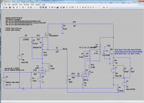
Well, I've got 3db difference in the output of the two channels according to Audio Tester.
Probing around I see the driver stages are responsible. Measuring components I don't see anything to account for it.
DC Anode voltages are within 1V of each other. Current through the 2K resistors in the gyrators match closely.
Swapping tubes has no effect.
Probing around I see the driver stages are responsible. Measuring components I don't see anything to account for it.
DC Anode voltages are within 1V of each other. Current through the 2K resistors in the gyrators match closely.
Swapping tubes has no effect.
Attachments
- Home
- Amplifiers
- Tubes / Valves
- Another SE amp design.