May an off topic,
does someone point me on the #12 message: Who is the supplier or brand of those large blank alum cap's having AMP term (without any isolation)?
Thanks
HpW
does someone point me on the #12 message: Who is the supplier or brand of those large blank alum cap's having AMP term (without any isolation)?
Thanks
HpW
Capacitor, 40uF, the supplier has other values as well:
eBay - New & used electronics, cars, apparel, collectibles, sporting goods & more at low prices
Clamp:
20PCS Capacitor Clamp Holder, 2" / 51mm. | eBay
eBay - New & used electronics, cars, apparel, collectibles, sporting goods & more at low prices
Clamp:
20PCS Capacitor Clamp Holder, 2" / 51mm. | eBay
Last edited:
Good morning!
I can not help than what I've done, but with GU50 tube, of course if you do PSF for 6P41S can successfully use it.
If it is useful, it is schematics used by me and works very well, is very stable.
I think MU-FALOWER tubes [ECC82, EF80] you can find it easily because they are classic tubes, but I think they also have Russian equivalents.
The schematic are posted all values of voltage and currents in the essential point.
I hope something will be helpful.
A good day!
Thank you LAZAROIU,
I didn't try your model last night as my hard drive is full and I need to do cleanup.
I tried something similar in Nov of last year in post 33 here:
http://www.diyaudio.com/forums/tubes-valves/200384-closed-loop-stability-help-needed-4.html
I also tried it with a tube as the control element as in in post 37.
I found the screen control (recommended to me by Waveborn) was more stable than the regulated cathode feedback method I had been using.
The stability issue I had was subharmonic (less than 1Hz) oscillation.
I still need a few spacers to mount the boards, and need to mount some terminal strips before I can start wiring it.
Hopefully I can get back from taking the granddaughter to weight lifting before the only real local Electronics Store closes. And, I hope they have the spacers I need.
Once I have everything placed, I need to decide if I'm going to paint the chassis (Black?) before mounting the wood cover or not. I don't think blue (sue to the blue transformers) or red would work with this one.
Canary Yellow?
Attachments
Hi,
thank you for the links...
But those are Motor Bike caps!!! May they fit not the required audio or high end specifications... low ESR vs Freq., Cap vs Freq.
May google for : Selecting and Applying Aluminum Electrolytic Capacitors for Inverter Applications from Sam G. Parler, Jr. Cornell Dubilier
While I am looking for a 1200uF /450V for my Cary SLM-100, there are very expensive once at Farnell (as the Sprague brands up to 80$ each)
regards
HpW
thank you for the links...
Capacitor, 40uF, the supplier has other values as well:
eBay - New & used electronics, cars, apparel, collectibles, sporting goods & more at low prices
But those are Motor Bike caps!!! May they fit not the required audio or high end specifications... low ESR vs Freq., Cap vs Freq.
May google for : Selecting and Applying Aluminum Electrolytic Capacitors for Inverter Applications from Sam G. Parler, Jr. Cornell Dubilier
While I am looking for a 1200uF /450V for my Cary SLM-100, there are very expensive once at Farnell (as the Sprague brands up to 80$ each)
regards
HpW
No. they are Motor Run Capacitors for applications like Air Conditioner motors, etc. They are self healing low ESR metalized film capacitors.
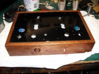
Baby in the cradle
All major h/w in place and no show stoppers. There were one or two 'interference' fits but that was all.
I need to buy new switches. The ones I have are on-off-on DPDT and I do not like the possibility of accidentally leaving them in the center position with a no connect.
All major h/w in place and no show stoppers. There were one or two 'interference' fits but that was all.
I need to buy new switches. The ones I have are on-off-on DPDT and I do not like the possibility of accidentally leaving them in the center position with a no connect.
Attachments

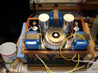
I've got the ac input circuit, line filter, Power Transformer, and bias supply wired in.
I decided to test it before proceeding as it is easier to fix now than after installing the rest of the circuitry.
Estimated power consumption is 75W, so I chose a 1A fast blow fuse for protection.
The problem is it blows fuses. I went through three trying to isolate the problem and finally decided it is the AnTek 1T200 toroid transformer. I switched to a 3A fast blow fuse and no problems.
Is this a characteristic of toroid power transformers, high inrush current?
I suppose inrush current is caused by charging filter capacitors.
I routinely install in my amps relay and 10-20 Ohm wirewound resistor in series with primary, powering relay coil from rectified filament DC. When capacitors charged relay shunts out that wirewound inrush limiter.
I routinely install in my amps relay and 10-20 Ohm wirewound resistor in series with primary, powering relay coil from rectified filament DC. When capacitors charged relay shunts out that wirewound inrush limiter.
No rectifiers or filter caps in the system other than the 470uf on the 24V transformer for grid bias voltage. Certainly that can't account for such an inrush.
I'll stick a NTC thermistor in the line to the fuse and see if it fixes it. Although it may not when I add the B+ rectifiers and filters.
I'll stick a NTC thermistor in the line to the fuse and see if it fixes it. Although it may not when I add the B+ rectifiers and filters.
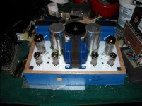
Left Channel is up and running.
WAF is already high. She heard "Have a heart" by Bonnie Raitt and said it sounded really nice.
Good attack on percussions. Vocals are nice with presence. strings are clean.
Even on 30 year old cheesy speakers it sounds good. I'll finish the other channel and move it to the den and try it on good speakers later this week.
Attachments
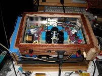
I finished the amp tonight and I must say it sounds better than any other amp I own.
It will take a while to break it in and do some serious listening in the different modes it supports (U.L. vs Triode strapped output, and Current Source loaded Triode Strapped 6J9P vs Mu stage with two 6J9Ps for the driver stage).
That said, it is plenty loud. I measured 85dB in the shop at 6' from the speakers (two playing) with it cranked all the way up and driven by a computer CD player. I also measured my normal listening level for comparison and it is about 60dB fast response, C weighted for both.
Both coupling caps (Inter-stage and Mu Stage) are K40Y. Resistors are FLAMEPROOF NTE 1W except the power supply and cathode resistors which are 2W. Iron is GXSE15-8-3.5K which provides a better low end than the smaller Iron which is rated closer to the amp output ability. Considering that I would describe the components as MID-FI, I'm amazed at how good it sounds.
First impressions are the Mu Stage is a bit bright wrt CS loaded triode mode 6J9P.
U.L. is of course louder, but not a great deal louder compared to Triode mode 6P41S.
The amp presents a consistently good sound stage in all modes (something none of my other SS amps even approach).
Speakers for initial testing are Radio Shack drivers from around 1978 in Panasonic Infinite Baffle enclosures from 1969 stuffed with acoustic battens around 1978.
I still need to build a set of enclosures for a pair of FF125WKs for the garage since I gave my granddaughter my FE103s, but other things get in the way.
I'll move the amp to the den and hook them to the Hersey speakers as soon as I get a chance (wife has declared that we are going camping this weekend, so I gotta get the camping equipment out and check it).
Did I mention the amp kicks ASSCOT?😀
My first amp is on loan to my daughter and SIL.
I'm finally getting around to building another amp and am going to make a variant of this amp.
This was prompted by another thread on a 6P41S amp:
http://www.diyaudio.com/forums/tubes-valves/266700-se-ul-6p41s-ussr.html
I started playing around with a breadboard of the output today and was amazed tofind I could drive the tube to 33W plate dissipation before it started to red-plate. The red was very consistent and even across the plate fins, which is very good.
It looks like 28W might be a reasonable max dissipation (85% red plate).
One difference between my design and Jean Michel's design is that I'm running fixed bias while he is running cathode bias.
Last edited:
One issue I've seen with the 6P41S is the tendency to oscillate when Ia > 60mA. On my breadboard it oscillates at 166KHz when I get above about 65mA.
A 500pf cap and 1K resistor (Zobel) in series across the transformer primary snubs this.
I've also found it necessary to use ferrite beads on the screen and grid terminals.
This shows up as harshness on "S and F" , particularly on female vocals.
A 500pf cap and 1K resistor (Zobel) in series across the transformer primary snubs this.
I've also found it necessary to use ferrite beads on the screen and grid terminals.
This shows up as harshness on "S and F" , particularly on female vocals.
I noticed similar phenomenon with several sweep tubes, but only in pentode connection.
Therefore I guess that the reason may be long wires and other stray capacitances which are typical when breadboarding.
Therefore I guess that the reason may be long wires and other stray capacitances which are typical when breadboarding.
This may well be true. I suspect teh low frequency is indicative of the coupling capacitance and seconary inductance of the transformer resulting in sufficient phase shift to cause the oscillation.
I will start doing the layout for the final amp and see how it behaves. I will leave room for the zobel in case it is necssary.
I will start doing the layout for the final amp and see how it behaves. I will leave room for the zobel in case it is necssary.
I've completed one channel of the power supply and tested it and have started the second channel. Rather slow progress, I must say.
That said I'm at my daughters and her family for the holiday and the original amp is still running fine. They run it several hours per day as it interfaces to their TV which is also the connection to their apple music account. When they are not watching tv the music is on.
They occasionally (or more often) forget to turn the amp off so it is on more often than they listen to it. I would estimate that they have over 5000 hours on it so far.
They have requested a circuit that turns it on when the TV is on and off when the TV is off. I'm thinking of something like a 555 with the trigger input capacitivly coupled to the audio with a long time out of say 5 minutes to avoid shutdown during times of low volume.
I think you can easily buy a 'smart' power strip that detects a load on the master outlet and switches the remaining outlets.
- Home
- Amplifiers
- Tubes / Valves
- Another SE amp design.