I'll go looking, but who is Victor if I don't find him?
Zapbuzz, thanks for the PM, look for my reply.
I mentioned in a note to Zapbuzz that I have a full CNC shop with mills and lathes. I also have tons of high quality poly caps (and others) many high voltage. I have many, many sprague tantalums, 150D NOS, orange drops, blue drops, bumblebees, etc, etc. Some guy sold me his Tek and HP repair stock. I think I paid $200 for about $40k of parts. I added up just the sprague tantalums at low, low ebay prices and it came to some "pay off the kids school loans" kind of number. I've been sending bags to friends. As I mentioned to zapbuzz, if there is an opportunity to do a joint build on something and we use my component footprints, we might save some money. The only thing about these parts is the many are axial, not radial. Like all the 150Ds you see all of HP gear. By the way, I don't think I have ever had one of them fail. I have had some orange drops fail. They go 'bang' like a .22.
I was active here years ago and then lost my email address to pac bell/att merger and rejoined in 2014. I can't remember the project from 2014 but around then is when my son blew my amp. Just a rambling bit more detail on the KSA50S, the high voltage is soldered to the rails (+/- like 50V or something) and I needed a really big soldering iron to re-solderit. But what happened was all that current across a not so great soldering joint with about 1ohm of resistance heated the joint until the solder melted and the lead fell out. I wish it had just reflowed... I wonder how many amplifiers can do that? reflow themselves?
He is Vicnic here on Diyaudio. I'm on a phone so limited in links. The end of the great "Low distortion oscillator" thread has more on his boards.
quick question while I'm here. Do analyzers generally measure THD continuously or measure, stimulate, measure? Is there a standard protocol for how they work or should work? I know the weighting filters and test frequencies have standards but what about how the various measurements are made? I know it shouldn't make a difference, but how do you know the harmonic you are looking at has harmonic energy other than comparing it to a baseline?
I have to go do some more reading I guess. this will be one of those dumb questions I'll kick myself for asking when I read the replies. ha!
Thanks
I have to go do some more reading I guess. this will be one of those dumb questions I'll kick myself for asking when I read the replies. ha!
Thanks
Most traditional analyzers are real time indicators. The computer types measure analyze and display. They can do this on a continuous basis but it's a delayed process and sometime a measure multiple times process and then display process.
quick question while I'm here. Do analyzers generally measure THD continuously or measure, stimulate, measure? Is there a standard protocol for how they work or should work? I know the weighting filters and test frequencies have standards but what about how the various measurements are made? I know it shouldn't make a difference, but how do you know the harmonic you are looking at has harmonic energy other than comparing it to a baseline?
I have to go do some more reading I guess. this will be one of those dumb questions I'll kick myself for asking when I read the replies. ha!
Thanks
One thing to point out is that most traditional analyzers provide an output of the distortion residual waveform and amplitude; i.e., all that is left over after the notch takes out the fundamental. This permits one to see the distortion waveform on a scope, along with the noise. It permits a judgement call as to how much of the THD+N is noise and how much is actual distortion. It further permits one to make a judgement as to the relative amount of second and third-order distortion there is in many cases. It is especially valuable in seeing crossover distortion. Finally, it permits the distortion to be further analyzed by a spectrum analyzer and can permit distortion measurement largely in the absence of noise. This is especially valuable when making distortion measurements at low power levels, like 1 watt and below. Many FFT-based distortion analysis tools and instruments do not provide a distortion residual output
Some of this is discussed in my book. Also, on my website can be found the original 3-part construction article from Audio magazine for my THD analyzer. It provides a fairly good explanation of how traditional distortion analyzers work. I use that distortion analyzer heavily to this day.
Cheers,
Bob

An FFT-based analyzer shows every harmonics + THD + THD+N, i.e. the harmonics are individually separated from the noise. Is it less convenient? I am learning the practical aspects, thanks.
An FFT-based analyzer shows every harmonics + THD + THD+N, i.e. the harmonics are individually separated from the noise. Is it less convenient? I am learning the practical aspects, thanks.
Yes, and this is a good thing. It just often does not show the real-time distortion residual.
Cheers,
Bob
The distortion residual display is the special value of DiAna. I don't know of other fit analyzers that can do that.
I do not understand this - a good analog notch filter will have let's say 60dB attenuation. Harmonics at -100dB will be still 40dB below the fundamental in such waveform view - that is just a few pixels at 800x600 resolution.
In digital processing the "notch filter" can be significantly steeper.
I could add the fundamental subtraction into my compensation software. Fundamental is being determined precisely by sine curve fitting (amplitude, frequency and phase against the head of the buffer) every 250ms cycle, it can be "compensated" out just like any other harmonics. The analyzing software downstream will receive samples with the fundamental subtracted. If it can display a waveform, it will display the residuals.
Actually both fundamental and all harmonics determined in the cycle can be subtracted, leaving only the noise and spurials for the downstream analyzer, should such an output make sense.
In digital processing the "notch filter" can be significantly steeper.
The distortion residual display is the special value of DiAna. I don't know of other fit analyzers that can do that.
I could add the fundamental subtraction into my compensation software. Fundamental is being determined precisely by sine curve fitting (amplitude, frequency and phase against the head of the buffer) every 250ms cycle, it can be "compensated" out just like any other harmonics. The analyzing software downstream will receive samples with the fundamental subtracted. If it can display a waveform, it will display the residuals.
Actually both fundamental and all harmonics determined in the cycle can be subtracted, leaving only the noise and spurials for the downstream analyzer, should such an output make sense.
I do not understand this - a good analog notch filter will have let's say 60dB attenuation. Harmonics at -100dB will be still 40dB below the fundamental in such waveform view - that is just a few pixels at 800x600 resolution.
I think there's a second filter to extract the residual - a non-critical active notch plus a multi-pole Butterworth high-pass wouldn't be hard to implement. Active notch would have enough Q to not depress H2 too far but not so much that frequency drift is an issue. Maybe Bessel filter is needed for lower phase error in the residual.
Bob's comments lead to another useful possibility. Take the 'residual output' of something like an HP339A and feed that into an FFT analyzer ( hp3562A recently mentioned or computer 'sound card'). That will help you further sort things out. With some work you might be able to calibrate it and with a low-distortion source be able to get good measurements. (I think AP may do something like this with some of their products)
Thanks, Bob, I'll go back and read the build and book. This is all very interesting. I guess I misunderstood how these analyzers worked. They notch out the fundamental and sum the rest. I was thinking they did successive harmonic energy readings from the FFT like I do with a spectrum analyzer. I know see that as being much more complicated than necessary and would have been impractical with any analyzer.
Playing around today with SpectrumLab, is there is an easy way to calculate THD from the db readings? Spectrumlab also has a sinad function with variable notch I was comparing against. For instance, if I stimulate the system with 1v peak and I see a fundamental of -10db, with 2nd, 3rd, 4th, 5th of -96.4, -99.1, -110.7, -104.9, do I have to convert them to voltages or can I calculate the THD from them more easily?
Getting back to summation of the system after the notch vs FFT, which is preferred? Telling me to read the book is fine as well.
thanks again.
Jerry
Bob's comments lead to another useful possibility. Take the 'residual output' of something like an HP339A and feed that into an FFT analyzer ( hp3562A recently mentioned or computer 'sound card'). That will help you further sort things out. With some work you might be able to calibrate it and with a low-distortion source be able to get good measurements. (I think AP may do something like this with some of their products)
Yes, I very often run the residual into a spectrum analyzer, often my analog HP3580A. It is a great analyzer, but only goes up to 50 kHz. You can see way down below the noise with this approach. I've often thought of running the residual into my DSO, which has a very wideband spectrum analysis funtion, but only 8-bit A2D. But even 8-bit A2D can be useful when you are just looking at the residual. This approach would allow viewing THD-20 harmonics out as far as the THD analyzer's bandwidth can go (200 kHz for a 20 kHz fundamental for my analyzer).
Cheers,
Bob
Still I mean even the Asus loopback. I have never seen such noise figure for a soundcard, let alone an internal one.
Phofman,
Last week arrived here a NU Audio card by EVGA (180$ card). This card is newer than ASUS Essence STX and has an advantage: sampling rate higher (384kHz).
I replaced the "audiophile" amp pop ( at line output for an LME49990 x2 and the THD and SNR were improved a lot.
The ASIO driver is not working properly so, initially, I´m using ASIO4ALL.
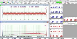
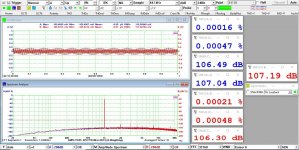
Below are the loopback tests, one is the best THD spot and the other is the best SNR spot (different line levels).
The THD numbers are worse than the ASUS ones, but SNR is better and the card is unshielded in a PCI-e extender over the bench. When I shield it, the numbers would be better.
Regards,
Attachments
Apologies for reviving an old thread, but I have been reading this thread over and over again and I thought this was the best place to post. I was fascinated by Bob's design of the THD analyzer, but also by Giulianodes work. I used both these excellent designs to make yet another version of the THD analyzer. I wanted to preserve Bob's original design as much as possible while making it completely uC controlled. I took Giulianodes' design one step further: he used analog switches for switching the relays, my design controls everything with shift registers controlled by a microcontroller. These shift-registers control all the relays (a lot!) on the boards. I also use a LCD display and seven-segment displays for displaying all measurements read by the ADCs. The project is in active development now, the uC board and PCB1 and PCB2 have been tested and they do work, currently busy with PCB3. I would love if more people would join in on this fascinating project, I sure could use some help getting all this to work and to improve on things, I am willing to share PCBs if anybody wants them (they come in batches of 5, I only need 1), I will publish an update to PCB1 and PCB4 (the uC board) shortly to correct some errors that were found. Anyway, have a look at https://github.com/Emile666/THD_Analyzer for details. Love to hear from you. Cheers, Emile.
Thank you for your kind words about my THD analyzer. I can't believe it has been over 40 years since I published its design as a construction project in Audio magazine. For those unfamiliar, that article is available on my website at cordellaudio.com. Technology has advanced greatly since then, and has permitted many improvements to the original design, most of which you are employing to make the design better, less expensive and more practical for builders.
One of the big things in the original design that has always stood out as a shortcoming was the use of very large multi-gang rotary switches and the related wiring to them. Back then, those switches were expensive and not that easy to find. So the use of relays on the board in place of them is a great improvement. It looks like you have incorporated a great many really good improvements to the design, and I thank you for that.
Cheers,
Bob
Bob, your article describing the design of the THD analyzer is written with so much attention for details. That makes it relatively easy to add a digital switching part, because the analog part is just so well engineered.
Just one question though: the signal generator works fine, I am using the uC to select a frequency, just by pressing a key. I even programmed a sweep mode into it, If I record the results (future work), you could off-load the entire sweep into a file for further processing. The signal-generator currently stops at 160 kHz, I tried other opamps (OPA1612) with higher bandwidth and slew-rate and had the CKM4/CLN4 caps mounted close to the opamp itself and increased their Q-enhancement compensation resistors to 330 Ohms. All these things in itself worked, but I still couldn't get the 160 kHz and 200 kHz frequencies to work. You mentioned slewing oscillations caused by a power-on transient for frequencies above 100 kHz. That is probably what's happening here. What are your thoughts on this? What could I do to get these frequencies to work as well?
Just one question though: the signal generator works fine, I am using the uC to select a frequency, just by pressing a key. I even programmed a sweep mode into it, If I record the results (future work), you could off-load the entire sweep into a file for further processing. The signal-generator currently stops at 160 kHz, I tried other opamps (OPA1612) with higher bandwidth and slew-rate and had the CKM4/CLN4 caps mounted close to the opamp itself and increased their Q-enhancement compensation resistors to 330 Ohms. All these things in itself worked, but I still couldn't get the 160 kHz and 200 kHz frequencies to work. You mentioned slewing oscillations caused by a power-on transient for frequencies above 100 kHz. That is probably what's happening here. What are your thoughts on this? What could I do to get these frequencies to work as well?
Hello, Emile,
I'm sorry to hear you are having trouble with the oscillator at 160 kHz and above. Getting the analyzer to work at 160 kHz can be a tall order, and I'm not sure that I know of other THD analyzers that go that high. I just checked mine, and it does actually work up to 200 kHz, with a residual that has risen to about 0.3 % at 200 kHz, and the auto-tune still working. Most THD distortion analyzers made these days are all-digital, with DACs in the source path and ADCs in the analyzer path, and using FFTs to reasure the distortion. This is totally logical and adds a lot of flexibility (I have a QuantAsylum QA403 and really like it). However, the digital analyzers can be a little more limited in how high they can go in frequency due to DAC and ADC sampling frequency limitations. Even sampling at 384 kHz, one can only see harmonics of a 20 kHz fundamental up to about 80 kHz.
Getting back to your problem with my analog THD analyzer, I do recall it being a bit of a challenge getting everything to work well up to 20o kHz. As you know, the state variable oscillator and filter pass the signal through 3 op amp stages in their loop, where excess phase can develop. This includes the two integrators. Moreover, my analyzer used 5534 op amps. They are atually very good for instrumentation, even though they are about 40 years old and no longer considered the best for audio performance. However, the 5534's were not unity-gain internally compensated - they were adequaly compensated for circuits with noise gain down to about 2 (I think, if I recall correctly). For unity gain compensation, they needed an external compensating capacitor. this helped a little bit, but of course the integrators are unity gain circuits. The resistors used in series with the integrating capacitors helped this a bit, reducing some of the excess phase. The first thing I would do in your circumstance would be to use 5534 op amps, since I had no experience with these other (fine) op amps back then. Not sure what else I can suggest at this point, other than playing around a bit with the external compensation of the 5534's and the integrating capacitor series resistors.
Cheers,
Bob
Wow, 40 years since I built my analyzer from that article. It's the most complex and best thing I've ever built and still works great to this day. I have an 8903 but Bob's unit can outperform it. The rotary switches were a PITA to acquire but patience and surplus outlets came through. Not sure it would be so easy today, but one might find something at hamfests. I had no trouble with the oscillator and think the board would make a very fine bench oscillator on its own.
Thanks for sharing this. I'm glad the analyzer has worked well for you. I still use mine also.
Cheers,
Bob
Cheers,
Bob
- Home
- Design & Build
- Equipment & Tools
- Another realization of Bob Cordell's THD Analyzer