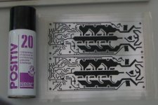
Ok, so here is the super hi-tech method I use to make PCB's.
Yes...seeing is believing, the image is printed on overhead transperancy and overlaid 3 times to get it black enough. Sticky tape holds it all together.
Positiv20 is a positive photoresist that is sprayed onto blank (and very clean) circuit board. I let the sprayed resist settle for about a minute or so then dry it in the wife's oven (just warm).
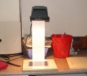
I then expose the image onto the PCB for about 20 minutes using a 500 watt halogen lamp (I know there are better ways to do this) with the glass removed to increase the UV output.
Surprisingly it all works quite well, with a perfect image every time.
Cheers
Yes it is German writing on the can. 6 cans were sent over by friends in Germany, I couldn't find it in Aus.
Yes...seeing is believing, the image is printed on overhead transperancy and overlaid 3 times to get it black enough. Sticky tape holds it all together.
Positiv20 is a positive photoresist that is sprayed onto blank (and very clean) circuit board. I let the sprayed resist settle for about a minute or so then dry it in the wife's oven (just warm).
I then expose the image onto the PCB for about 20 minutes using a 500 watt halogen lamp (I know there are better ways to do this) with the glass removed to increase the UV output.
Surprisingly it all works quite well, with a perfect image every time.
Cheers
Yes it is German writing on the can. 6 cans were sent over by friends in Germany, I couldn't find it in Aus.
Attachments
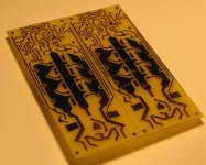
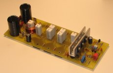
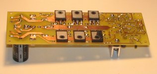
Here's an etched pair of boards ready for seperating, drilling and stuffing. If it all works this amp (6 FET version) will replace the modules in my PA.
The copper is dark beacuse the photoresist has been left on. It will be removed after the drilling.
Cheers
The copper is dark beacuse the photoresist has been left on. It will be removed after the drilling.
Cheers
Attachments
Nice to see the art of DIY PCBs is alive and well. I just find the drilling process rather mind numbing.
Having them made is still horribly expensive. 🙁
Having them made is still horribly expensive. 🙁
Hi quasi,
I love to see when people are really simply damn good! 😉
How did you apply the "Positiv 20"? I had only average results by simply spraying it on, while your etched board looks pretty void-free...
Good luck DIYing on. This one is my current favourite among the many solid-state DIY amp constructions, simply because You're doing such an incredible job. 😉
Ciao,
Sebastian.
You've got to be super clean with that sort of stuff. I always use pre-sensitised boards.
Have a look at the SENO PCB products, they are wipe on rather than spray on.
Have a look at the SENO PCB products, they are wipe on rather than spray on.
These are some of the things I do;
I store the Positive 20 in the fridge. Keeping it cold makes it last longer and it flows better when sprayed.
With the board flat I spray the Positive 20 so that it's just thick enough to flow by itself. This way it fills any holes. But not too thick. I let it settle for about a minute so that the sprayed layer smooths out.
Then I carefully place it in a just warm oven (6o deg C) for about 30 minutes. This makes the resist very hard.
The exposure time took some trial and error. With the lamp (which is the wrong lamp*) I have, 20 minutes gives good results. I print the image on my laser printer and use 3 layes of transperancy to get the image balck enough.
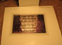
I develop the image in a weak caustic solution (2 minutes) then etch.
It took me some time to get it right, but I now get a perfect board every time.
And as BlackCat suggested the boad has to be super clean. I use metal cleaner with an abrasive pad and rub hard. Once the board is rinsed fingers are a no no.
Cheers
* I use an ordinary 500 watt halogen lamp. I removed the front glass to increase th UV output. A friend of mine has the right lamp (UV) and his takes only 5 minutes.
I store the Positive 20 in the fridge. Keeping it cold makes it last longer and it flows better when sprayed.
With the board flat I spray the Positive 20 so that it's just thick enough to flow by itself. This way it fills any holes. But not too thick. I let it settle for about a minute so that the sprayed layer smooths out.
Then I carefully place it in a just warm oven (6o deg C) for about 30 minutes. This makes the resist very hard.
The exposure time took some trial and error. With the lamp (which is the wrong lamp*) I have, 20 minutes gives good results. I print the image on my laser printer and use 3 layes of transperancy to get the image balck enough.
I develop the image in a weak caustic solution (2 minutes) then etch.
It took me some time to get it right, but I now get a perfect board every time.
And as BlackCat suggested the boad has to be super clean. I use metal cleaner with an abrasive pad and rub hard. Once the board is rinsed fingers are a no no.
Cheers
* I use an ordinary 500 watt halogen lamp. I removed the front glass to increase th UV output. A friend of mine has the right lamp (UV) and his takes only 5 minutes.
Quasi,
I doffs me cap, your work is extremely high quality, with every attention paid to detail, detail detail - this is production quality, no question!
1 Question: why did you go for a different drive system on your other quasi-comp, rather than the Seimens topology Michael refined? Do these amps sound different, or is it too early to know?
Cheers,
Hugh
Thanks again Hugh,
I built this type of topology (siemens) before many years ago. A friend and I developed the circuit and built quite a few. That design used a cascode first and second stage, because of the high voltage rails we wanted to use. Incidentally the one that I built runs rails of +/- 92v. There are about 20 (stereo units) of these floating around Adelaide.
But I was never entirely happy with it. It could have been the PCB layout, case wiring or something else, but the amp was noisy (low level hum and hiss) and whilst it delivered lots of power it was only suitable for party - PA - instrument work.
So I decided to try something else and went for the other topology. I like the symmetry of the second stage in that cct and results have been very good. That amp sounds great, is absolutely quiet and has very little distortion. The project also prompted the PCB layout I am now using; you'll notice that the PCB's between that project and this one are very similar. This layout style offers quite a compact PCB.
During that project I also discovered 2SC1845's, a high voltage, quiet transistor, so it was goodbye to cascode stages.
Anyway the outcome of that amp plus the contribution of other members during that project has encouraged me to approach this design again using the layout learning from the other one.
So I hope this PCB layout and the brilliant ideas contributed in this thread will fix the old problems. I guess I'll know soon enough.
Cheers

That looks great quasi. The output inductor looks quite big though? Also quite large (decoupling) caps?
construction help
Hi quasi, i've followed the entire post and i'm interested to build this amp for my subwoofer.
Hi have some irpf250. Can ibuild this amp using them?
And, how to adjust VR1 and VR2?
Sorry for my english.
Thanks
Hi quasi, i've followed the entire post and i'm interested to build this amp for my subwoofer.
Hi have some irpf250. Can ibuild this amp using them?
And, how to adjust VR1 and VR2?
Sorry for my english.
Thanks
Workhorse said:Hi Quasi,....
Nice PCB's...good work...
Why your +85V isn't floating with +VCC...you have ground referenced it.....any reasons for it...
richie00boy said:That looks great quasi. The output inductor looks quite big though? Also quite large (decoupling) caps?
Thanks guys,
I think the power supply will have less noise if it is returned to central ground. I did not want any ripple on the high current +ve rails affecting the other one.
The output inductor is 30 turns of 1mm wire. The capacitors are out of junked PC power supplies (read free).
Cheers & thanks again
quasi said:
I think the power supply will have less noise if it is returned to central ground. I did not want any ripple on the high current +ve rails affecting the other one.
Cheers & thanks again
Hi Quasi...
But then you would need a higher voltage rating capacitor indeed....
regards,
K a n w a r
Hi Flavio88
The 1K single turn trimmer (VR1) is used to adjust the output offset to zero volts. Just connect a meter to the output and adjust for less than 10mV.
The multi-turn trimmer (VR2) is used to set the bias current through the output. Before the amp is turned on set for maximum resistance. Then adjust for around 30mA per FET pair. This should be done with 10 ohm 5 watt resistors in place of the fuses. This way there if is anything wrong with the amp you won't blow the output FETs. Once the bias is set you can replace the resistors with fuses.
IRFP250 would be a good choice for this amp, depending on the power you require.
Cheers
Workhorse said:
Hi Quasi...
But then you would need a higher voltage rating capacitor indeed....
regards,
K a n w a r
Yeah, I using 160v ones. Tomorrow I will post the PCB layout for the PSU.
Cheers
- Status
- Not open for further replies.
- Home
- Amplifiers
- Solid State
- Another quasi-complementary design