Hi quasi !
I meant the configuration posted by lineup, using a floating cascode on the left leg of 2nd diffamp, keeping the vce for the devices there equal, but not constant. Typically, cascoding to constant vce does help with linearity, but somehow not in this topology... Yes, then you need powerful devices or drivers to the mosfets. With that many outputdevices you have a giant capacity to drive, but you need a quite high slewrate at these powerlevels.
Kanwar, i have not played around with your topology yet, but will do later...
Mike
Valued Opinions
Learned Gentlemen,
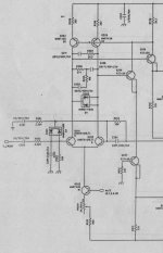
I wonder whether you could offer opinions, including benefits and issues for these 2nd stage options.
I don't have any sim applications and if you have the time I would value this information also.
Sincere Thanks
Quasi
Learned Gentlemen,
I wonder whether you could offer opinions, including benefits and issues for these 2nd stage options.
I don't have any sim applications and if you have the time I would value this information also.
Sincere Thanks
Quasi
Attachments
Hi quasi !
I think it's more like option #5... The 22ohms i added are optional.
But mje350 might be too weak, mje15033 is not a too fast device, i don't know which device is best here.
You might consider a driverstage to the mosfets ? Then you could keep the mje350...
Option 3 does not work like that, you must put a cap paralell to the 4.7k and discard the 2.2k.
Option 2 also does not work, the Vce for T6 is quite small, this 1.8k resistor will give ~20v creating negative Vbe for T7/8.
Mike
Attachments
Michael, Quasi,
I think I like #5 too. It is beautifully configured to ensure that Vce and AC voltage swings on each of the two VAS devices are identical. This is probably as good as it gets, and it ensures that the compensation is applied symmetrically.
The best bipolars to use for both VAS and cascode would be 2SC4793 and 2SA1837, which are 100Mhz/70Mhz respectively and rated to 2A with very low junction capacitances and 150V/20W rating. These should be sufficient with rail voltages to about 70.
Commendable, Quasi/Michael. Really good solution!
Cheers,
Hugh
Hi, Mike,
Where is this #5 coming from? Very good indeed, but I don't see it in Quasi's options (only 4 of them)?
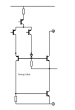
How about combining it with Kanwar's second stage? It has no emitor connected to rail supply, the PSRR and speed should be good with Kanwar's
Where is this #5 coming from? Very good indeed, but I don't see it in Quasi's options (only 4 of them)?
How about combining it with Kanwar's second stage? It has no emitor connected to rail supply, the PSRR and speed should be good with Kanwar's
Hi, Mike,
How about this connection for connecting differential and VAS? R236+Q204/205 makes the whole thing much more stable.
Q207 replaced by idea #5.
Quite different from Quasi's original, the bias setting is put in the differential CCS, and thermal compensation is Q204-205 placed on heatsink.
How about this connection for connecting differential and VAS? R236+Q204/205 makes the whole thing much more stable.
Q207 replaced by idea #5.
Quite different from Quasi's original, the bias setting is put in the differential CCS, and thermal compensation is Q204-205 placed on heatsink.
Attachments
Whoa ...
Hi Folks,
MikeB...you are so clever. Thanks. The MJE350's will easily handle the 18mA per leg with around 90 volts Vce.
Now before I move on, I don't fully understand why my original cascode using the FETs would not perform well. Please forgive my ignorance but I'm in sales and marketing by day and a pure hobbyist by night (no commercial audio bent at all)*
The reason I say this is because the cascode stage ensures that there is around 4 volts across both the BC556's i.e the same voltage. That to me says that voltage symmetry is maintained and a lower voltage means lower noise and easier (more linear?) switching...
So what am I not getting ?
Cheers
*Day time skills exceed night time skills.
Haaah ! LOL.
Let me assure you, there are two things I always carry.
1. Fast calculator
2. Sharp Pen.
Even things like Boeing Aircraft are sold by ....ready to cringe?.....sales people.
But I started life as an tech .....guess it never left my system.
Cheers
Let me assure you, there are two things I always carry.
1. Fast calculator
2. Sharp Pen.
Even things like Boeing Aircraft are sold by ....ready to cringe?.....sales people.
But I started life as an tech .....guess it never left my system.
Cheers
lumanauw said:Hi, Mike,
How about combining it with Kanwar's second stage? It has no emitor connected to rail supply, the PSRR and speed should be good with Kanwar's
Hi David THE LUMANAUW,[Do you know GOLIATH]😀 😀 😉
Due to no emmiter connected to power rails the PSRR is >120dB
and the Slewrate is also >100v/uS...Impulsive Transient Punching , high voltage swings are easily obtained...
Bandwidth is also >500kHz
Gain is enormous, therefore one can make a great use of high feedback factor to reduce the distortion as well..although local feedback is also present...which IMHO is good thing....
One could also use parallel transistors for higher current drive & low impedance for the gates of mosfets....
K a n w a r
Hi, Quasi,
Nice one 😀
You have put C5-R6, maybe you can get rid of C8-C9?
Maybe you can make one version with Kanwar's second stage? Good PSRR can benefit the sonics.
Nice one 😀
You have put C5-R6, maybe you can get rid of C8-C9?
Maybe you can make one version with Kanwar's second stage? Good PSRR can benefit the sonics.
Re: Version 3v1
Quasi, i have not sim'd your whole circuit, i was mainly observing the vas. I think, build it !
Lumanauw, you're funny ! 😉
Mike
quasi said:
Mike, have you simmed this ?
Quasi, i have not sim'd your whole circuit, i was mainly observing the vas. I think, build it !
lumanauw said:Good PSRR can benefit the sonics.
Lumanauw, you're funny ! 😉
Mike
AKSA said:I think I like #5 too. It is beautifully configured to ensure that Vce and AC voltage swings on each of the two VAS devices are identical. This is probably as good as it gets, and it ensures that the compensation is applied symmetrically.
Commendable, Quasi/Michael. Really good solution!
Cheers,Hugh
lumanauw said:Hi, Mike,
Where is this #5 coming from? Very good indeed, but I don't see it in Quasi's options (only 4 of them)?
How about combining it with Kanwar's second stage? It has no emitor connected to rail supply, the PSRR and speed should be good with Kanwar's
I guess I am a bit to blame for this idea.
See my Post #123
http://www.diyaudio.com/forums/showthread.php?postid=810128#post810128
I was happy to hear Workhorse (Kanwar) knew more about this way
and to find that MikeB liked the idea.
Myself has never tested this in real circuit,
but the idea I got when theoretically (paper and pen) exploring ways
to make this kind of N-Channel amplifiers.
Must have been like 10 years ago.
Attachments
Hi, Mike,
Lineup just a few days ago also said that top opamps gives good PSRR.
MikeB, I'm confused now 😀 Could you share your opinion about PSRR and audio amp sonics?
Is that PSRR not related to good sounding? Amplifierguru say(s) this, he even have a paper on Electronics World+Wireless World December1990, "Distorting Power Supplies", talking about this.Lumanauw, you're funny !
Lineup just a few days ago also said that top opamps gives good PSRR.
MikeB, I'm confused now 😀 Could you share your opinion about PSRR and audio amp sonics?
Lumanauw, your word "can benefit" was way to harmless, in fact high PSRR is one of the keys to a good sounding amp... High PSRR is mandatory. An amp with low PSRR connected to weak powersupply will distort as hell with odd harmonics, no matter of how much feedback it uses.
Mike
Mike
lumanauw said:Hi, Mike,
Is that PSRR not related to good sounding? Amplifierguru say(s) this, he even have a paper on Electronics World+Wireless World December1990, "Distorting Power Supplies", talking about this.
Lineup just a few days ago also said that top opamps gives good PSRR.
MikeB, I'm confused now 😀 Could you share your opinion about PSRR and audio amp sonics?
I did some research of my own.
On Op-amps.
What I found was, that price of an OP was strongly related to PSRR.
OP-amps used in very high performance ( in figures ) circuits
had all very high PSRR.
There are some very expensive that often are regarded as 'best':
AD797, OPA627, LT1028, LT1015
They all have high PSRR, often 100dB or more.
OP-amps not recommendable for high performance audio
have mostly PSRR lower than 70dB.
They do not cost much.
We have a group in between, at 70-100dB,
they do not cost too much and are not too bad for audio.
Now high PSRR and good figures, does not have to make a good sound.
But a correct and good application using OP-amps with high PSRR
would have better chance to make a good sound quality.
- Status
- Not open for further replies.
- Home
- Amplifiers
- Solid State
- Another quasi-complementary design