Hi Hugh !
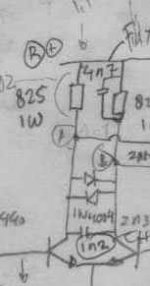
These clamping diodes are not across r4/5, between them. Under normal operation they would never conduct. But when the amp clips, the first LTP will saturate, creating large voltages here, in this case these diodes will prevent the 2nd diffamp entering reversebias conditions. I stumbled into this problem when i was working on a high power version of symasym, also using cascodes for the 2nd diffamp.
Mike
Greetings Michael,
Ah, yes, I realise they are between them; my wording was poor, my mistake.
At clip, eh? That's remarkable, shows the feedback network is trying hard to compensate the clipping and swinging the LTP to full excursion. Hadn't realised that would happen.......
Thanks for the tip!
Cheers,
Hugh
Ah, yes, I realise they are between them; my wording was poor, my mistake.
At clip, eh? That's remarkable, shows the feedback network is trying hard to compensate the clipping and swinging the LTP to full excursion. Hadn't realised that would happen.......
Thanks for the tip!
Cheers,
Hugh
quasi
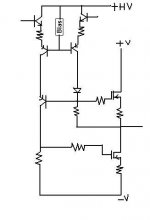
this is an old idea I have had, but havent tried yet
I have attached a drawing using bipolar
it is another attempt to 'cascading' VAS pair
in this type of N-Channel amps
to give this pair equal working condition
if it is of any use in this your project, I do not know
but I really would like to get my idea tested
by myself or somebody else
I think it may work
but
are there any advantages?
can there be any major drawbacks?
Attachments
Welcome to the Quasi party guyZ
Hello HUGH DEAN,
Have a look at the attached photo...
No second differential...
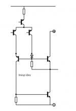
Emmiter followers driven from first input differential ..inturn drives cascodes for voltage amplification & also reduces thermal drift and third single cascode facilitates symmetric drivability during high voltage swings ..& thus keeps the OLG much symmetric...
Please let me know about your views...
I implemented this topology in high power amp with VCC at + -130VDC.....The output Damping Factor [>1000@8 ohms]and High frequency response [100KHZ]was very astonishing.....Rail Loss was 0.55V....Mosfets were 12 pairs of APT30M85BVR..Driver Tansistors were BF471/472 video application 400V Bipolars
You were absolutely correct..the diodes were necessary to sustain nice operation during heavy clipping...
Well said LINEUP, this type of implementation is already in use with ECLER N-Channel amps www.ecler.com and also we use it exclusively...very good response
K a n w a r
AKSA said:Quasi,
Just a few ideas, don't know if they are useful....... I'm sure Kanwar has lots of answers on this, so I'll defer to him.
Cheers,
Hugh
Hello HUGH DEAN,
Have a look at the attached photo...
No second differential...
Emmiter followers driven from first input differential ..inturn drives cascodes for voltage amplification & also reduces thermal drift and third single cascode facilitates symmetric drivability during high voltage swings ..& thus keeps the OLG much symmetric...
Please let me know about your views...
I implemented this topology in high power amp with VCC at + -130VDC.....The output Damping Factor [>1000@8 ohms]and High frequency response [100KHZ]was very astonishing.....Rail Loss was 0.55V....Mosfets were 12 pairs of APT30M85BVR..Driver Tansistors were BF471/472 video application 400V Bipolars
Hi MikeB..MikeB said:Hi Hugh !
These clamping diodes are not across r4/5, between them. Under normal operation they would never conduct. But when the amp clips, the first LTP will saturate, creating large voltages here, in this case these diodes will prevent the 2nd diffamp entering reversebias conditions. I stumbled into this problem when i was working on a high power version of symasym, also using cascodes for the 2nd diffamp.
Mike
You were absolutely correct..the diodes were necessary to sustain nice operation during heavy clipping...
lineup said:quasi
this is an old idea I have had, but havent tried yet
I have attached a drawing using bipolar
Well said LINEUP, this type of implementation is already in use with ECLER N-Channel amps www.ecler.com and also we use it exclusively...very good response
K a n w a r
Attachments
I can make some simulations this evening regarding different cascoding. My BJT-version of this topology without any cascodes already showed "only" ~1.5%THD openloop at 20khz, 15v swing into 4ohms. (84db OLG)
It did not show any visible symptoms of different phasehifts/delays for upper and lower half. Regarding the simplicity of this topology it performs very good !
I did not finish my version because of the symasym...
Mike
It did not show any visible symptoms of different phasehifts/delays for upper and lower half. Regarding the simplicity of this topology it performs very good !
I did not finish my version because of the symasym...
Mike
Re: Welcome to the Quasi party guyZ
thanks, Workhorse
Yes, I had my guess it had been used before.
Nice to hear it can work well.
Workhorse said:Well said LINEUP,
this type of implementation is already in use
with ECLER N-Channel amps www.ecler.com
and also we use it exclusively...very good response
K a n w a r
thanks, Workhorse
Yes, I had my guess it had been used before.
Nice to hear it can work well.
Hi Hugh,
Thanks for your posts thus far and for your input, which I am reading carefully.
The main rational for the cascode second stage was;
1. I thought that by limiting the voltage on T5 & T7 this stage would be faster and quieter by virtue of the lower voltage across CE. Without T9 & T8 the voltage across T5 & T7 would not just be very high but also asymmetric.
2. Finding a fast, quiet and robust transistor that could handle just over 180 volts across it with currents of around 18mA and potentially up to 36mA whilst dissipating almost 3.5 watts was tricky. I would actually like to run the second stage at around 40-50mA but things get a bit warm.
I take your idea of resistors instead of the T8 & T9 with interest. I don't actually like cascodes with zeners finding them a little noisy.
Thanks also to MikeB, Lineup and Kanwar for their ideas and comments at the Quasi Party ?
Regarding these diodes. About a year or so ago while setting the bias (10 ohm resistors in fuse holders) I decided to look at the max swing with no load on my CRO. When I cranked it up to severe clipping (practically square wave) the amp latched. The results were of course disastrous. I wonder whether if I had the diodes.....
Cheers
lumanauw said:Hi, MikeB,
Are these diodes what you mean? Switzerland's FM Acoustics 611 uses 2xIN4004 there.
Yes ! But, 1N4004 is bad choice here, high speed and low capacitance like the 1n4148 is a way better choice. With slow diodes recovery from clipping might be bad.
Mike
Hi, Mike,
I'm 100% agree with you.
I just got confused. Why does that USD50.000 power amp use that?
I'm 100% agree with you.
I just got confused. Why does that USD50.000 power amp use that?
lumanauw said:Hi, Mike,
I'm 100% agree with you.
I just got confused. Why does that USD50.000 power amp use that?
Hmm, maybe USD50.000 is not automatically good / well engineered ? Or that powerful that it is not driven into clipping normally.
Or this diffamp uses very high currents ?
Mike
Hi, Mike,
It a mystery to me 😀 Like other "small matter" mysteries. Why NP likes ordinary diode instead of MUR diodes? Why the old WE 300B is said sounds better, while the new WE 300B has better material implied? Why some designs uses 5% carbon resistor, not 1% metal film resistor, and sounds better? Why some designs uses plain R instead of transistor CCS? Why some designs still uses ceramic caps, while it is known that ceramic caps are the worst? Why some still use R divider for making a voltage reference? What do customers hear, and still buy a "wrong" design, even it is very expensive?
It a mystery to me 😀 Like other "small matter" mysteries. Why NP likes ordinary diode instead of MUR diodes? Why the old WE 300B is said sounds better, while the new WE 300B has better material implied? Why some designs uses 5% carbon resistor, not 1% metal film resistor, and sounds better? Why some designs uses plain R instead of transistor CCS? Why some designs still uses ceramic caps, while it is known that ceramic caps are the worst? Why some still use R divider for making a voltage reference? What do customers hear, and still buy a "wrong" design, even it is very expensive?
Hi quasi !
I ran some simulations in openloop, the cascode configuration lineup has posted performed best, the configuration when cascoding both devices in 2nd diffamp was way worse. (visible distortions)
Maybe you should use some heatsinked to126 devices for 2nd diffamp ?
Mike
I ran some simulations in openloop, the cascode configuration lineup has posted performed best, the configuration when cascoding both devices in 2nd diffamp was way worse. (visible distortions)
Maybe you should use some heatsinked to126 devices for 2nd diffamp ?
Mike
Hi MikeB,
Sorry you have confused me slightly. I read your response as;
"the cascode configuration as posted performed best"
then I read
"when cascoding both devices in 2nd diffamp was way worse"
I think though that you're suggesting that I lose T7,T5, T8 & T9 in the second stage and simply use more powerful transistors. Is that correct?
Can you please try to explain again.
Cheers

Hi Kanwar,
This is a Rush Cascode, named after Christopher Rush in 1964. It is very rarely used in audio, but has stratospheric gain (giving very high feedback factor) and DC to light bandwidth.
I have experimented with it in SE in a Class AB PP amp some years back, but couldn't get it to sound good. Obviously with mosfets you have made it work.
I did find that a small resistor between the NPN/PNP emitters pulled back gain and extended linearity, but I doffs me cap to anyone who can get it to work reliably and sound good!
Cheers,
Hugh
Hi AKSA...
Well said Hugh...
Besides this I have another topology much superior than this , which uses no additional elevated rails to get rail to rail swing..with drivers forming with BC558/548 complementary PP pairs driven from Bootstrapped Supply seperate for upper & lower rails .....All small signal Trannies just to drive the MOSfets....
K a n w a r
Hi, Kanwar,
It is really a good idea. It can replace VAS differential, without current limiting (by R or CCS). Without current restriction, it helps transient very much.
Once I make something like that http://www.diyaudio.com/forums/showthread.php?s=&threadid=37866&highlight=
The gain is very big with this approach, like AKSA said.
Hi LumanauW,
Thats why I used it to drive the Mosfets to get +-130V pk2pk...
High Slew rate was inherent necessity when you want to obtain large voltage swings of magnitude greater than 100 volts....
K a n w a r
Thats why I used it to drive the Mosfets to get +-130V pk2pk...
High Slew rate was inherent necessity when you want to obtain large voltage swings of magnitude greater than 100 volts....
K a n w a r
- Status
- Not open for further replies.
- Home
- Amplifiers
- Solid State
- Another quasi-complementary design