To return to Thel (Thomas Hartwig+), the man has been dead for years! His expertise is still relevant! He doesn't sell any power filters; his daughter-in-law only sells the remaining stock of his circuit board designs, either as DIY kits or raw boards. Personally, I can only recommend these filters for source devices, as his circuit boards also suffer from dynamic losses in front of power amplifiers. His explanations and measurements are very good, however, and shouldn't be dismissed as uninteresting and commercial for those of you discussing the topic.
It's true that interference is constantly changing, but there is a clearly defined frequency range in which interference occurs, and this needs to be attenuated with a filter! The relevant range is between 1 kHz and 100 kHz. This interference is caused by switching power supplies, LEDs, and solar panels, and is easy to attenuate. I'm not even talking about RF filters above 10 MHz, where passive attenuation is more of a lottery!
I simple ferrite can stop the Mhz, it's very easy
What I don't understand is the perceived loss of dynamics, and why can't you measure it
In a PS you turn 60hz into 20khz and 20 hz So I don't see where 2khz interference from a coil low pass and such could reduce dynamics, inductors in a XO have ridiculous cut off like 1khz and phase shift but it doesn't reduce dynamics? why a line filter could
A 5V drop in the main on a properly built amplifier will take many seconds to reduce gain and should never be heard no more than the 60 hz.
The problem is DC , asymmetry and radio waves...
And fluctuating voltages from morning to evening around 3V which is enough to change the critical manual bias in amplifier by a little.
If it does reduces dynamics WHY can't it be measured?
I propose take a square wave 1khz reading at low and high power, repeat with the filter/variac and see if it is more slopped calculate the slew rate before and after.

Today I measured an isolation transformer (no label on it about VA, I guess around 200VA from weight) at various situations:
First measurement with seconday winding open, primary winding with a 50Ohm resistance in series:

We see that the voltage going into the primary winding is transferred 1:1 to the secondary winding up to about 10kHz, then the gain increases together with an increase in phase into the positive direction. The maximum gain around 50kHz stems very likely from the self-resonant behaviour of the EI core, where winding capacitance takes over.
In the next measurement the secondary winding is loaded with 50 Ohm:

In contrast to the open secondary winding, the 50 Ohm load is transferred to the primary winding, the ingoing signal is attenuated by about 3.3dBV up to about 1200Hz, which is roughly the -3dB point of the increasing attenuation with a slope of about 20dB/decade. The inductive behaviour changes around 140kHz to a capacitive behaviour.
In the next measurement I added a 0.33uF capacitor at the primary in order to simulate some X2 input filtering:

The addition of the X2 capacitor had no effect except above 200kHz, where some resonances might occur.
What are the conclusions?
1) An isolation transformer attenuates in fact at quite low frequencies. A toroid transformer might do this as well (to be verified by measurement!)
2) The attenuation will depend strongly on the (ohmic) load on the secondary side (make R_load 100 Ohm?).
3) Adding capacitance at the input of the isolation transformer had negligible effects on the attenuation below 100kHz
4) Regarding HF (which starts conventionally around 30MHz): very likely (no data shown!) no effect because of working above the self resonance.
First measurement with seconday winding open, primary winding with a 50Ohm resistance in series:
We see that the voltage going into the primary winding is transferred 1:1 to the secondary winding up to about 10kHz, then the gain increases together with an increase in phase into the positive direction. The maximum gain around 50kHz stems very likely from the self-resonant behaviour of the EI core, where winding capacitance takes over.
In the next measurement the secondary winding is loaded with 50 Ohm:
In contrast to the open secondary winding, the 50 Ohm load is transferred to the primary winding, the ingoing signal is attenuated by about 3.3dBV up to about 1200Hz, which is roughly the -3dB point of the increasing attenuation with a slope of about 20dB/decade. The inductive behaviour changes around 140kHz to a capacitive behaviour.
In the next measurement I added a 0.33uF capacitor at the primary in order to simulate some X2 input filtering:
The addition of the X2 capacitor had no effect except above 200kHz, where some resonances might occur.
What are the conclusions?
1) An isolation transformer attenuates in fact at quite low frequencies. A toroid transformer might do this as well (to be verified by measurement!)
2) The attenuation will depend strongly on the (ohmic) load on the secondary side (make R_load 100 Ohm?).
3) Adding capacitance at the input of the isolation transformer had negligible effects on the attenuation below 100kHz
4) Regarding HF (which starts conventionally around 30MHz): very likely (no data shown!) no effect because of working above the self resonance.
5) The tests were not done with the transformer directly connected to 230V mains voltage.
Last edited:
50VAC is considered dangerous.What if it has a 50v then you touch ground, probably nothing will happen
Yepp, but what would you expect to be different from 8Vpp input?5) The tests were not done with 230V mains voltage.
Is the attenuation the same for common-mode and differential-mode interference?Today I measured an isolation transformer (no label on it about VA, I guess around 200VA from weight) at various situations:
First measurement with seconday winding open, primary winding with a 50Ohm resistance in series:
View attachment 1442400
We see that the voltage going into the primary winding is transferred 1:1 to the secondary winding up to about 10kHz, then the gain increases together with an increase in phase into the positive direction. The maximum gain around 50kHz stems very likely from the self-resonant behaviour of the EI core, where winding capacitance takes over.
In the next measurement the secondary winding is loaded with 50 Ohm:
View attachment 1442406
In contrast to the open secondary winding, the 50 Ohm load is transferred to the primary winding, the ingoing signal is attenuated by about 3.3dBV up to about 1200Hz, which is roughly the -3dB point of the increasing attenuation with a slope of about 20dB/decade. The inductive behaviour changes around 140kHz to a capacitive behaviour.
In the next measurement I added a 0.33uF capacitor at the primary in order to simulate some X2 input filtering:
View attachment 1442411
The addition of the X2 capacitor had no effect except above 200kHz, where some resonances might occur.
What are the conclusions?
1) An isolation transformer attenuates in fact at quite low frequencies. A toroid transformer might do this as well (to be verified by measurement!)
2) The attenuation will depend strongly on the (ohmic) load on the secondary side (make R_load 100 Ohm?).
3) Adding capacitance at the input of the isolation transformer had negligible effects on the attenuation below 100kHz
4) Regarding HF (which starts conventionally around 30MHz): very likely (no data shown!) no effect because of working above the self resonance.
What happens when direct current is superimposed on alternating current?
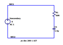
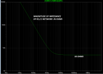
Hi @Grauwacke , you can greatly reduce the power dissipated in your 50 ohm damping resistor, by noticing that the resonant hump only begins to appear at 10 kHz and above. So it's possible to install a capacitor in series with the 50 ohm resistor and achieve huge reductions of the current & power dissipation at the (very much lower) mains frequency. Here's an example.
_
_
Attachments
Servus Franz,Is the attenuation the same for common-mode and differential-mode interference?
What happens when direct current is superimposed on alternating current?
my guess is that there wont be a difference, when a DC component (acting as common-mode) is added to the AC, as long as the transformer works within its linear region of the magnetization curve (i.e, the transformer must stay far away from saturation, which will leave some remanent magnetization on the core, once the magnetic field is switched off).
@Mark Johnson : I will measure that, thanks for the comment.
Currently, a toroid is measured (each measurement takes about 20 minutes...)
And here the promised measurement of a 250VA toroid, measured in reverse direction: input into secondary (24V), out (230V) loaded with 560Ohm. Gain starts at about 18.2dBV. which corresponds to the winding ratio of 230/24=9.58; 20* log (9.58) = 19.6dBV

1) Several resonances above 50kHz.
2) Onset of attenuation at much higher frequency than the isolation transformer (EI core)
3) Maximum attenuation much smaller than that of isolation transformer
4) Filtering of toroid transformer seems less efficient than of EI core (is it a function of wattage? => check)
Last edited:
The critics of the 50Ohm:50Ohm measurements are old, as the paper says, but one needs standardized conditions for not comparing apples to peas. The 0.1/100 and 100/0.1 Ohm measurements provide further details, of course, but who knows the source impedances of the mains connections up into the MHz region? So finally, as noted in on the Thel homepage: It depends!
Furthermore, may I note that a transformer is not directly comparable to a LC filter. What I measured was only the transfer function of the primary side to the secondary side. In detail more measurements would be necessary: The leakage inductance, the magnetizing inductance, the DC resistances, the intra and inter winding capacitances; parameters, which are all accessible by measurements, see the attached pdfs.
Btw, I would never rely on some "filtering action" of a transformer because it is not its purpose and there exist much, much better ways to get rid of AC pollution (e.g., the R21 module or the various regulators of Jan and others).
Attachments
Last edited:
Which apples to which peas? Testing a random unknown brand/type EI transformer of unknown power rating and a random unknown brand/type 230V:24V 250VA toroid (not the discussed 230V:230V isolation version) used in reverse on 24V produces leading data? Both unknown/unnamed DUT also not used in 230V setup with nominal load. We learnt that they are transferring LF signals of 8Vpp rather well (till a certain frequency) besides the 50 Hz they are meant for. That is what transformers do for a living. Revelation: they can even be used as output transformers for 20...20 kHz audio.
The tests show exactly that both exhibit indeed some kind of filtering in the area of interest. What is not mentioned: isolation transformers generally also reduce leakage and reduced sensitivity to pick up radiated garbage.
So conclusion could be that they do filter and provide galvanic isolation but are best helped by an added mains filter and an RF proof PSU. Instead of spending years on one aspect have a combination to fight pollution. A pollution that changes randomly so why not fight it somewhat at all fronts?
Last edited:
In my two measurements I tried to normalize the testing conditions: For the isolation transformer R_load was set to 50Ohm (source impedance of the sine generator), for the toroid in reverse the 560Ohm equal about the source impedance after considering the impedance transformation due to the winding ratio. So voltage level and impedances could be seen as roughly comparable in both sets, but, of course, are far from any real world situation. Btw, are impedance measurements done at 230V AC right into the MHz region available?
"So conclusion could be that they do filter and provide galvanic isolation but are best helped by an added mains filter and an RF proof PSU.
... A pollution that changes randomly so why not fight it somewhat at all fronts?"
Fully d'accord with you.
"So conclusion could be that they do filter and provide galvanic isolation but are best helped by an added mains filter and an RF proof PSU.
... A pollution that changes randomly so why not fight it somewhat at all fronts?"
Fully d'accord with you.
Exactly,
Ideally : a big inductor filter in the HOT --- DC Blocker (diodes/caps) then // filters : bobins/ coils/ bobins, then UHF caps then output
Output to Isolation or in my case Toroid to control main voltage variations to your amp.
I now have a 8.5 A and an 13.5 A output Transformer, a 2kvA and 3kvA, using 250vA is not a good idea
Which brings us back to the dynamic loss caused by coils! Large coils also usually have higher internal resistances
My point is that an increase of a few ohms of the AC should not affect anything if the power supply is already in the order of a few more ohms, and that it Should be easy to measure.
As I said, there is no difference for a regulated supply.
If the power supply is unregulated what difference does it make? I think we a square wave we could see.
But the square wave is already very unperfect on an amplifier designed for music.
Let's measure the difference also from the gain difference between a low signal and large signal and repeat through the power supply, if the difference is 0.05db it should be acceptable
- Home
- Amplifiers
- Power Supplies
- Another EMI filter