The most important thing in an EMI filter are the coils, these must have a particularly high permeability and a very low internal resistance, smaller coil values and very large X2 capacitors are best in order to achieve a lower cutoff frequency of the filter, be careful with Y capacitors, too high values can trigger the FI!


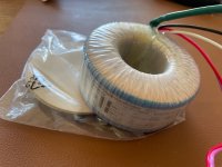
The last picture shows a Chinese DC filter and EMI filter board, which sits directly in front of the transformer in a ChipAmp amplifier.
The last picture shows a Chinese DC filter and EMI filter board, which sits directly in front of the transformer in a ChipAmp amplifier.
Last edited:

Here's a link to a page with good explanations of DC filters and EMI filters!
https://www.thel-audioworld.de/module/Netzfilter/Netzfilter.htm
https://www.thel-audioworld.de/module/Netzfilter/Netzfilter.htm
Trenntransformatoren erhöhen den Stromkreiswiderstand zu sehr! Darüber hinaus ist es problematisch, ein Gerät der Schutzklasse 1 hinter einem Trenntransformator anzuschließen.Ein Trenntransformator, insbesondere ein EI-Kern-Trenntransformator, ist eine sehr effektive Komponente für den Einsatz in einer Reihenschaltung von EMI-Filtern. Groß, schwer, teuer und effektiv.
Isolation transformers increase the circuit resistance too much! Furthermore, it is problematic to connect a device of protection class 1 behind an isolation transformer.
No. Not at all really. Maybe you make a mistake by thinking of isolation transformers with a secondary middle point connected to PE. Those are outright dangerous.
Normal isolation transformers allow touching of both L or N (Ahem, never both) while standing with bare feet on the ground without risk of electrical shocks. PE is still used but N is separated from PE. Metal casing is of course connected to PE.
Medical equipment makes use of them. For enhanced safety.
Last edited:
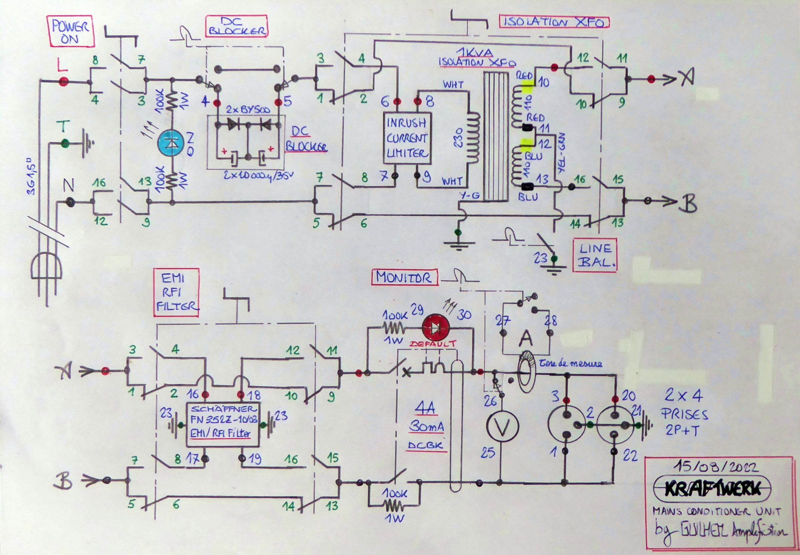
Yes. Though I'm not strictly in that order. I included some other features - all defeatable - but no Variac nor regulation :
1- DC blocker.
2 - inrush current limiter.
3 - isolation transformer and -10VAC step down (mains is always too high at home).
4 - line earth balance.
5 - EMI/RFI filter.
6 - output protection.
7 - current and voltage monitoring.
You halve the capacitor values by connecting the positive poles opposite each other! It's more effective to connect the electrolytic capacitors in parallel and also a film capacitor (X2) in parallel. Two diodes in series increase the DC filtering by up to 3 volts.
Okay, that's true. However, the internal resistance is too high to drive a power amplifier behind it; there will be dynamic losses. To avoid that, you'd need a 4kV isolation transformer, and that's not practical. A better approach is to use very small coil values and large capacitors.No. Not at all really. Maybe you make a mistake by thinking of isolation transformers with a secondary middle point connected to PE. Those are outright dangerous.
Normal isolation transformers allow touching of both L or N while standing with bare feet on the ground without risk of electrical shocks. PE is still used but N is separated from PE. Metal casing is of course connected to PE.
Medical equipment makes use of them.
If you only use it for source devices, it's fine, but you'll experience some dynamic range loss in front of a power amplifier. I've been building power filters for over 20 years, and it's never been any different!
The only viable way is to use nanocrystalline high-permeability coils (e.g. Vitroperm from Vakuumschmelze) with very low internal resistance and very large X2 capacitors

For example, Puritan Laboratories doesn't use nanocrystalline coils, which can also filter common-mode noise. Therefore, Puritan must use large common-mode coils to filter common-mode noise, which increases the filter's resistance.

If all that is supposedly needed I better choose none. Just the device connected straight to mains like it originally is supposed to be connected 🙂
It is just business selling such stuff. It is not a lab but a home I live in too.
It is just business selling such stuff. It is not a lab but a home I live in too.
A DC filter and EMI filter eliminate mains interference. If the mains is heavily contaminated, a filter can improve the sound. However, if the filter's design is poor, then I agree with you. Back to isolation transformers: I still wonder what the point of grounding is, since an isolation transformer is a new circuit in the secondary section; nothing is discharged to ground, and you don't need to protect yourself with grounding, either, since this circuit itself doesn't discharge anything to ground. This protective circuit is also the reason why isolation transformers are used in operating rooms in hospitals!
Of course, filter solutions with isolation transformers are also possible, but the effort is very high, as can be seen, for example, with Aude's filters.
https://www.audes.de/audes-dt-3600-power-conditioner.html
https://www.audes.de/audes-dt-3600-power-conditioner.html
Here's another link to a review of Aude's isolation transformers:
https://audio-freak.de/marken-empfe...9Wjx9hWLC1CZYIjJPvVZBVEO_MorE-O9WB_93Nr-7LP5x
https://audio-freak.de/marken-empfe...9Wjx9hWLC1CZYIjJPvVZBVEO_MorE-O9WB_93Nr-7LP5x
You need grounding because of the PS is connected to the amp case (metal) and there are stray return currents in it.
Connecting the PS ground neutralize it and reduce any risk of shock and helps the fuse blow in both input and PS side.
I don't know how dynamics could be affected by using a VARIAC which is 15 Amperes with for example a tube amplifier.
I want to use the tube power amp with the variac to get the best bias possible and more stable voltage.
I think in a properly designed amplifier the power supply has more output resistance relatively than the input AC , a few more OHM would not cause audible difference I think. But it has to be measured how much the AC voltage drops during peaks vs idle.
Everything you wrote is correct. Of course, a metal enclosure with a transformer must be grounded unless it's designed to meet protection class II standards. On the other hand, grounding has no effect on the secondary section (after the secondary winding) of an isolation transformer or adjustable isolation transformer (variac), because the transformer is galvanically isolated. It's a separate circuit that doesn't drain to ground!
What if it has a 50v then you touch ground, probably nothing will happen
- Home
- Amplifiers
- Power Supplies
- Another EMI filter