Ideally it would be a RF,EMI filter, followed with DC blocker (diodes and caps) + Variac + regulator to stabilize the AC
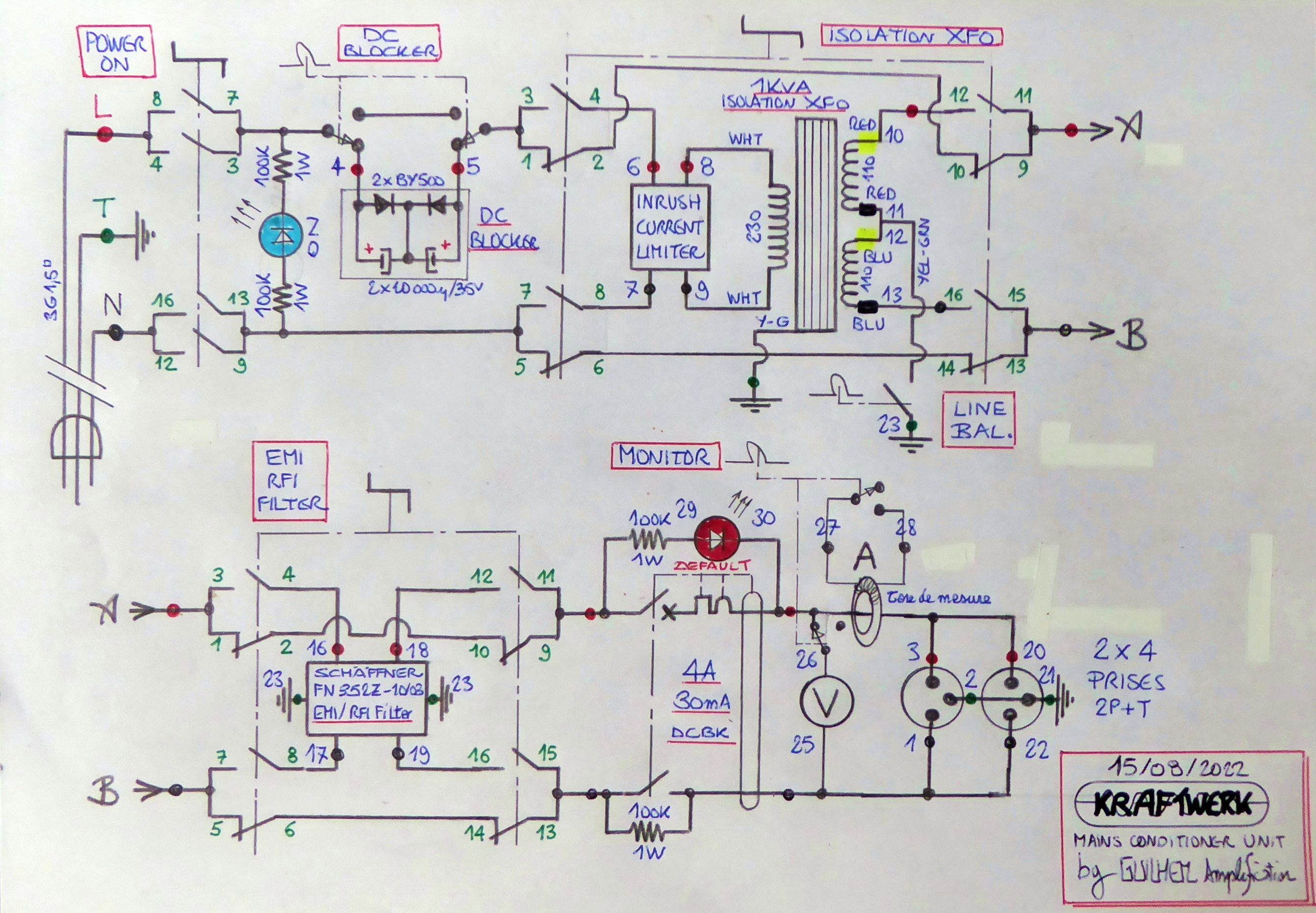
Yes. Though I'm not strictly in that order. I included some other features - all defeatable - but no Variac nor regulation :
1- DC blocker.
2 - inrush current limiter.
3 - isolation transformer and -10VAC step down (mains is always too high at home).
4 - line earth balance.
5 - EMI/RFI filter.
6 - output protection.
7 - current and voltage monitoring.
T

I have some experience with this... now that you mention it, we have around 245-250v from the outlet here (living near a distribution transformer, maybe out of specs), and some of my old equipment (220v rated) does not really work properly. Transformers overheating or buzzing, but the worrying part is the secondary voltage getting too high and going beyond the specs of the components. I was lucky that some of them had another 240v winding for Australian outlets but not all of them are adjustable, and that circuit would be quite ideal.10VAC step down (mains is always too high at home).
The worst case I had was an amplifier reaching 88-90v on the secondary after rectification while the main caps were all rated 80 volts
Last edited:
If you start with this Chinese garbage, it's a big step forward.
Proper filtration is designed for a specific situation. Something general cannot solve certain problems and does more harm than good.
Proper filtration is designed for a specific situation. Something general cannot solve certain problems and does more harm than good.
A big step backwards, I think. Who knows the real specs of those components and capacitors and their quality, as people mentioned before good quality components cost more. We talked about this here when I suggested using those boards in post #57 and the idea got quite disapproved for good reasons.
Plus you have no idea if they followed strict design rules for making the PCB and enough clearance.
That's why we are making our own circuit.
Plus you have no idea if they followed strict design rules for making the PCB and enough clearance.
That's why we are making our own circuit.
Last edited:
I bought two on Amazon, I have a chinese variac and it works very well, I don't have over a thousand dollar to purchase one made in USA.
Yes. but at the price... I bought my chinok modules and my chinok variac soon, I doubt it is going to be less performing than that.
First, my variac will be 20 Amps , bigger,
Second, I wont need a soft start, I will place the voltage to exactly what I need, and the 50 A diodes will support the soft start already incorporated in my amplifier.
Third, I think my chinese module will have more filters,
Fourth, I don't need 5 outputs etc, i just connect the power bar into the single case I will make for my module, but great box, I appreciate your dedication and all the wires.
Mine will be soldered, no screw terminals.
You still have to do the notations for the component values.
I hope I didn't make a mistake... I did it quickly. 🙂
In the future, take care of the symmetrical arrangement of the components. If I can help you with anything else, I am at your disposal.
A list of the components used would also be necessary.

I hope I didn't make a mistake... I did it quickly. 🙂
In the future, take care of the symmetrical arrangement of the components. If I can help you with anything else, I am at your disposal.
A list of the components used would also be necessary.
Attachments
Splendid! Thank you very much, I will do everything and post the gerber file when it's done. A few people got interested and want to build the filter now.
Thanks again for your time and dedication.
Thanks again for your time and dedication.
You don't need to use traces (you can, thin ones to follow designations for CA), you can draw copper area, and that way you can utilize more space and more precisely 😉You still have to do the notations for the component values.
I hope I didn't make a mistake... I did it quickly. 🙂
In the future, take care of the symmetrical arrangement of the components. If I can help you with anything else, I am at your disposal.
A list of the components used would also be necessary.
View attachment 1435773
I'm not at my pc, but i found an image via google search that can ilustrate. When there is a large surface and you need as wide a copper trace, you use copper area (large wide "trace" on image), where you can freehand draw and use maximum space to connect two or more components.

I don't know if you saw the previous PCB version, but that's what I did, by hand using copper areas. Of course it's more time consuming and you need to keep an eye for possible weak spots, so In this case I suspect Julian redid it with the normal routes for extra safety, correct me if I am wrong.You don't need to use traces (you can, thin ones to follow designations for CA), you can draw copper area, and that way you can utilize more space and more precisely 😉
- Home
- Amplifiers
- Power Supplies
- DIY EMI filter for power supply