One should avoid creepage and possible accidental touching of mains voltage carrying parts, contacts that stick out one way or another as much as possible. The good thing is that this is also free. There are no valid reasons not to do so.
Please mind that this device may be powered on 24/7 its entire lifetime. Would not be my choice but it may happen. Dust/dirt/insects etc. Not virtual but real reality.
It can be good inspiration to check how a class II device has been built.
Please mind that this device may be powered on 24/7 its entire lifetime. Would not be my choice but it may happen. Dust/dirt/insects etc. Not virtual but real reality.
It can be good inspiration to check how a class II device has been built.
Last edited:

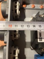
OK but it seems very inadequate for mains voltage devices supposed to be connected to 230V AC 16A house installations. Minimum 5 mm clearance the last time I checked. Can be even more today.
It has its merits in low voltage DC electronic circuits.
I'm sure you are mistaken as regarding to creapage distance. I belive per ipc 2221 for mains voltages, it is not necessary to go above 2mm spacing between conductors. Unless i didn't pay much attention at altium seminars, so could be wrong. These won't be abused in inhuman conditions.
I don't know if you saw the previous PCB version, but that's what I did, by hand using copper areas. Of course it's more time consuming and you need to keep an eye for possible weak spots, so In this case I suspect Julian redid it with the normal routes for extra safety, correct me if I am wrong.View attachment 1435816
That one looks much better for these purposes. If you have time, optimize it a little bit more.
Absolute minimum clearance/creepage numbers are absolute minimum clearance/creepage numbers. Reality and practical experience both dictate not to keep to absolute minimum numbers and definitely not in DIY mains connected stuff that has no certification/lab measurements. Keeping to absolute minimum requirements as design practice is nitwit practice asking for trouble. And really totally pointless as doing it with a margin costs nothing. Also there is nothing "too safe" and if it were it still would be preferred over "just enough".
Walk in the field and see insects causing short circuits between very close contacts, cement powder becoming conductor, dust the beginning of a carbon track on PCBs, air bubbles in isolation becoming the start of leakage etc. All not necessary but maybe the people at Altium seminars know better. Have a look at PCBs that have been powered on for years and see where the dirt builds up and eventually causes problems. Diagnose stuff that went booooommm and see why it happened.
Walk in the field and see insects causing short circuits between very close contacts, cement powder becoming conductor, dust the beginning of a carbon track on PCBs, air bubbles in isolation becoming the start of leakage etc. All not necessary but maybe the people at Altium seminars know better. Have a look at PCBs that have been powered on for years and see where the dirt builds up and eventually causes problems. Diagnose stuff that went booooommm and see why it happened.
Last edited:
I'm sorry but several edits on your post do not teach me anything proper. And i was "wrong" yes, but in a good way, ipc 2221 high voltage requirement (not a minimum) is 1.25mm spacing distance for this use case, so even less. And that is for up to altitudes to 3000m above sea level up to 300V. So 2mm is pretty much safe, especially when there is a dielectric costing on top of conductors to prevent dust and such bugs you mention. But ok, for the sake of diy and overenginnering stuff, 2.5mm rated for 500V is fair to say is just fine and dandy for this filter.
Ipc 2221 one is reality, not mumbo jumbo someone came up with, it is a regulation standard. Why would i need to show? Or you know better than people that set standards? You are simply wrong in this matter, and yes i belive altium guys do know better, world class engineers work there, and i'm very glad i met some and have the oportunity to learn from them.
Ipc 2221 one is reality, not mumbo jumbo someone came up with, it is a regulation standard. Why would i need to show? Or you know better than people that set standards? You are simply wrong in this matter, and yes i belive altium guys do know better, world class engineers work there, and i'm very glad i met some and have the oportunity to learn from them.
You've complicated yourself unnecessarily. The way you did the routing doesn't add anything.Julian redid it with the normal routes for extra safety, correct me if I am wrong.
Ja.
Viel Arbeit, aber ich wage zu bezweifeln, dass dieser Netzfilter sinnvoll ist
The positive effects outweigh the negative big time.
But it is best to use them with normal power amplifiers and not the silly 2 x 400W devices. Those with SMPS as usual today don’t feel the drawbacks you describe anyway. Real world power is in my case about 2 x 1….3W so no need for kVA stuff.
Sources benefit most. I use either 100VA or 150VA ones by Sedlbauer or Noratel medical ones. Direct improvement. Often better than just a mains filter.
Last edited:
Yeah, a 500va is not much for an amp, and could you measure the loss of dynamics, in a good amp there are many levels of capacitors, inductor and regulators , how can we measure the loss od dynamics also, voltages being constant
Hello hi I am still alive 😉Enough threadjacking. Please let's go back to the topic "DIY EMI filter for power supply" and the board. Where is our friend Mimiragon?
The boxes for the filters finally arrived today, so I am able to take a precise measurement for the circuit.
These are standard boxes for guitar pedals you can find online or on aliexpress. A few people in the DMs asked me to make things quite precisely so they can order the same boxes and have the filter fitting without problems.
(a bit off-topic but I made this blog where I will post from time to time my serious and less serious projects, I think I will document everything on both there and diyAudio once this filter circuit is done to keep track of everything from the start to the end)
Hi! Some remarks:
1) Are the sides of that casing slightly skewed? Then printing the PCB layout 1:1 and place it in the casing may reveal undesired details that require a change.
2) It can be handy to add footprints of other versions of the current parts so these can also be used.
3) Will it have a power on/off switch?
4) And does the width of the casing allow Schuko sockets? That would really be handy. The less error possibilities/lower contact resistance/cables the better. IEC C13 are an option but less desired I think. Anyway your filter will then also be a substitute of the standard plastic power distributor (in better quality).
5) Please consider to use M3 mount equipment feet 20 mm or the like. Cabinets will not be scratched and the device will not slip. The self-adhesive versions are generally so so.
I use these by Mennekes but they have become crazy expensive but sometimes show up on eBay for 4 Euro a piece. Look good and are good. In cast aluminium casings they can be mounted with countersunk M4.
Attachments
Last edited:
If I can send a sturdy power switch just let me know. I stock a few nice 22 x 30 mm DPST types that switch both L and N.
how deep do they go into the chassis? i wouldn't want them to interfere with the circuit below, so I must know the depth of them.I use these by Mennekes but they have become crazy expensive. Look good and are good. In cast aluminium casings they can be mounted with countersunk M4.
In my casing 16 mm but I would calculate with 21 mm and subtract the casings thickness. Then keep 4 mm clearance. The L and N screws are protected against wiring coming loose. Very nice german industrial quality but copies are sold.
The black version with PE but without cover is the Mennekes 11532. Screwless versions exist but these are inferior. The ones with spring closed cover look nice but are less ergonomical as they do not allow one hand plugging in of plugs.
BTW outside dimensions are 50 x 50 mm. Fixing holes at 38 x 38 mm.
https://www.mennekes.co.uk/product-details/panel-mounted-socket-schukor-11532/
Attachments
Last edited:
The 1032L skewed (!) casing allows 4 Schuko outlets with mains switch on the side (when used upside down for better looks and more ergonomic wiring). The switch will be at an ergonomic position but it can be skipped so a 5th Schuko can be mounted. That will result in wiring acrobatics 😀 Make sure you position the switch at an ergonomic position and also think of how to wire stuff without needing 4 hands. You can mill/drill/file the Schuko holes in the casings official bottom. Easy peasy with only 2.2 mm thickness. Then use the official cover as bottom plate with 4 x M3 holes at the corners for equipment feet. With 8 mm clearance from PCB to bottom plate you will have about 20 mm for part height counted from the PCB. With 5 mm standoffs about 23 mm. If you print the PCB design 1:1 you can see where the bottlenecks are, there is probably space enough between Schuko outlets for the larger parts.
*If you are creative you could add a plexiglass layer or let's say 4 mm thickness in a nice color and have 4mm less deep Schuko outlets. I strongly suggest to have it powder coated for sturdiness. A nice power distributor/mains filter will last for decades!
PS don't loose the screws as they are possibly non metric americano unusual stuff.
Attachments
Last edited:
Don't trust my judgment, I forgot PCB thickness. But you got the picture I hope. My versions are usually quite compact with 3 or 4 Schuko outlets as I have minimalist setups and not piling up of devices I practically never use. In the odd case of having an extra device a plastic power distributor with 2 x Schuko can be plugged in one of the Schuko outlets. Depends on the maximum allowable current of course.
With only 3 to 4 daisy chained Schuko outlets you sure can play with moving inductors (IF that is needed). The tremendous added value of functionality, sturdiness and filtering in a compact all in one format. With added safety as all stuff can be switched off 100%. Make sure to use a mains entry cable of the right gauge like 1.5 mm2 or even 2.5 mm2. It will likely meet my own standard of being able to fall from 1 meter and survive.
With only 3 to 4 daisy chained Schuko outlets you sure can play with moving inductors (IF that is needed). The tremendous added value of functionality, sturdiness and filtering in a compact all in one format. With added safety as all stuff can be switched off 100%. Make sure to use a mains entry cable of the right gauge like 1.5 mm2 or even 2.5 mm2. It will likely meet my own standard of being able to fall from 1 meter and survive.
Last edited:
I placed that DC +emi filter in my audio, still some crap interferences which goes through, but the sound is way better.
Here we have the Wifi, G3, G4, G5, satellite radio, Am, Fm, DEL street lights, Teslas and many more electric cars, Roof solar panels, There is so much pollution that it still persists after the filter,
Ill place the transformer on top of all this and see.
Ill wrap my Dac in metal mesh.
Here we have the Wifi, G3, G4, G5, satellite radio, Am, Fm, DEL street lights, Teslas and many more electric cars, Roof solar panels, There is so much pollution that it still persists after the filter,
Ill place the transformer on top of all this and see.
Ill wrap my Dac in metal mesh.
- Home
- Amplifiers
- Power Supplies
- DIY EMI filter for power supply