I've played with Heil AMT's and ribbons over the years, but the thought I have is to do a ribbon with a field coil. Have any diy'ers attempted this? My idea is to slit a pipe lengthwise and wind a coil in the hollow. The pipe's radius can also act as a simple horn as well. Ideas , pitfalls ?
@ fooeywuffle
The steel is used to focus the magnetic flux lines from the neodymium into the gap.
It is possible to do this as an air core motor. But will require much larger amounts of neodymium.
@ geraldfryjr
Possibly a massively parallel amplifier. They are useful for very low impedances and the ST chip TDA7293. Page 12 and page 15 in the application note covers it quite well.
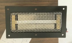
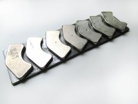
I finally finished the 4 inch ribbon tweeters. I figure 4 of them is enough! They were a lot of work to make look good. They are over twice as loud as any tweeter I have bought and a lot clearer.
Ray
____________________________________________
If brute force doesn't work, your not using enough of it!
Ray
____________________________________________
If brute force doesn't work, your not using enough of it!
Attachments
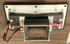
Very nice! Can you give us details on the frame the magnets are attached to and the transformer?
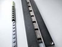
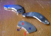
The frame is cheap 2 inch wide channel iron. Magnets sit at a slight angle, but I don't think that matters. Copper pins through sides holds magnets at the proper height. No need to glue them since the power of the N-52 is so strong, they aren't going anywhere.
Transformer: The size of the core is 2 3/16 inches square and no gap. It is wound based on RF tech, so not an easy job. For ribbon resistance of .03 ohm, which is what the ones I made are, the ratio is 17 to 1. just for 36 watts, that is 36 amps on secondary! I used 5 mil copper sheet that is wound so it is a tube when done. layer of foil, wind 16 turns of 2 ea #21, then another foil. Side ends are pinched together and soldered making it a flattened tube. 4 of these in series to complete it. The connection ends of both of the foils has a piece doubled over and soldered. This is because of the high current. I tested it for the amount of voltage it would take with little loss. For 3 Kc lowest frequency, it would take 35 volts RMS, which at 8 ohms is over 150 watts! The ribbon won't even handle that! This has almost 100 percent coupling, and very little loss.
If you want more photo's, and info sent request to fooeywuffle@yahoo.com
Attachments
Sorry to ask here but is it very expensive to make a 36" tall ribbon?
I only ask because I have been floating around the idea of either buying some TPL's, buying the 150's from Raal or make my own ribbon. While the DIY sounds like fun I am a bit in fear of wasting more money than it would cost to have the Raal's.
If this is the wrong place o ask this I am sorry also. Just trying to finalize my ideas and go from there.
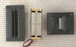
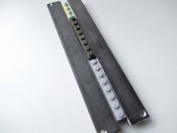
Here is one last picture. This one is the completed ribbon. All I have left to do now is wind another transformer and attach two lengths of "T" shaped aluminum that will serve as the mounting brackets. I should be able to easily complete it
Hi
Probably a stupid question does the primary go to the ribbon or the secondary?
The primary coil on the transformer is connected to the amplifier.It has many turns.
The secondary ,with few turns and thicker wire, goes to the ribbon.
Bernt
The secondary ,with few turns and thicker wire, goes to the ribbon.
Bernt
There are know....stupid question!......Can be a lot... stupid answers ....this is a ribbon ..so I would think.....hehe.... the secondary would be on the ribbons input...primary would be the input from the amp.....good luck
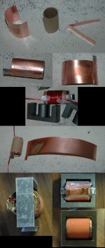
It's ribbon speaker maded from HDD's magnets. It's very simple and budget-friendly construction for DIY.
Attachments
-
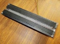 готовый.jpg152.7 KB · Views: 263
 -
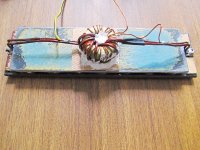 вид сзади.jpg914.5 KB · Views: 264
 -
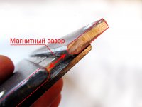 магнитный зазо
.jpg436 KB · Views: 250
магнитный зазо
.jpg436 KB · Views: 250 -
 лента пайка.jpg503.2 KB · Views: 230
 -
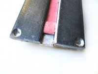 мягкая проклад
.jpg542.3 KB · Views: 387
мягкая проклад
.jpg542.3 KB · Views: 387 -
 лего вынуто.jpg611.4 KB · Views: 391
 -
 сборка с лего.jpg528.5 KB · Views: 400
 -
 установка на ма.jpg545.5 KB · Views: 407
 -
 с магнитами.jpg507 KB · Views: 423
Very inventive! How does it sound? Where did you get the ferrite core for the transformer? What is the effective impedance of the ribbon with the transformer?
It sounds good. Ring from a computer power supply. Impedance 4.75 Ohm/
The transformer contains:
25 turns of the primary winding, 0.65 mm in diameter,
3 turns of the secondary winding, with a diameter of 2x1.6 mm.
The transformer contains:
25 turns of the primary winding, 0.65 mm in diameter,
3 turns of the secondary winding, with a diameter of 2x1.6 mm.
Last edited:
It's ribbon speaker maded from HDD's magnets. It's very simple and budget-friendly construction for DIY.
A great way to think up and apply methods to make a great loudspeaker!
ky3ne4ik: Once i wanted to do the same with hdd magnets but i had no idea of the magnet arrangement, so i decided to make 4pi ribbon out of a ring magnet harvested from a microwave magnetron. It worked out pretty well except efficiency.
thx a lot for the idea, time to grab my hdd magnets sticking at my door frame 🙂
thx a lot for the idea, time to grab my hdd magnets sticking at my door frame 🙂

- Home
- Loudspeakers
- Planars & Exotics
- Another DIY Ribbon thread