Hi Denis,
My ears can sometimes hear the difference between 6u and 15u foils.
If you want to experiment with power tapering on your multi-ribbon line array it may be easier and sound more coherent to just put a non-inductive resistor in series with some of the ribbons. You can make a low ohm resistor by contact cementing household AL foil to plexiglass and cutting a serpentine pattern with an Xacto. Brass washers and screws make good contacts.
You may want to surf the web for articles on comb filtering in a line array vs. a continuous line source. There are also a few articles on Bezel function power tapering you might find interesting.
J.L.,linesource - I hadn't thought to try a shunt resistor. I'll certainly keep this in mind if I go with power tapering.
linesource - What kind of differences do you hear between the two thicknesses?
I've done a fair amount of reading on power tapering and understand the principle. I have seen many array with mid/woofs tapered but very few that do the same with the tweeters. I wondered if it was because high frequencies are much more directional than mid/woofers. This directionality may mean that you receive highs from a relatively smaller section of the array so comb filtering caused by interference caused by sound from the ends of the arrays is reduced. It's just a thought...
I will look for more info on Bessel (I assume you did not mean Bezel) function tapering. Thanks for the tip.
Regards,
Denis
Member
Joined 2003
Hi Denis,
More homework for you...just in case you get bored 🙂
Depending on crossover frequency (1k?) and listening distance, you may be getting into near field/far field transition with a 47" line. If so, you'll probably want to decide how to deal with it. (Depending on room noise, you may be able to see it by comparing ribbon frequency response at your listening position vs 1 meter.)
With a final ribbon length of 45" and a lower crossover I had decisions to make, but I won't know if my current strategy will work until final baffles are done and I can do more serious testing...and listening. I cut MDF last weekend and have finally started building something permanent...I hope 🙂
Paul
Hi Paul,
Thanks for the homework suggestion. I'm always happy when somebody finds something more I should do.🙄
 🙂
🙂
My primary listening position will be about 11 feet from the speakers (which will be on either side of my front projector screen). I decided on the size of my ribbon (~1.3 meters) based on the near field transition chart in Jim Griffin's excellent white paper. At my expected 1.5k crossover, the near field should be good out to about 4 meters. In any case I will certainly be doing some listening position measurements when I get ready to start on the crossover.
I've made a little more progress today. I got all the cross pieces installed and squared up. Now al l I have to do to finish is build a set of ribbon connectors and cut, pleat and install the ribbons.
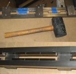
I've included a couple more pictures. The top shows the frame still clamped up with cross pieces installed along with my "adjuster". As I mentioned in a previous post, Once the cross pieces are placed on the poles they the magnet field makes it literally impossible for me to budge with my bare hands. This is where my rubber mallet comes in; A few whacks will usually get the cross pieces lined up with the threaded holes on the poke pieces.
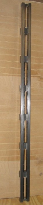
The second picture is just a detail of the front of the assembly, before I install the fiberglass connector blocks. These blocks will just sit on the cross pieces attached with super glue.
Thanks for the homework suggestion. I'm always happy when somebody finds something more I should do.🙄
🙂 My primary listening position will be about 11 feet from the speakers (which will be on either side of my front projector screen). I decided on the size of my ribbon (~1.3 meters) based on the near field transition chart in Jim Griffin's excellent white paper. At my expected 1.5k crossover, the near field should be good out to about 4 meters. In any case I will certainly be doing some listening position measurements when I get ready to start on the crossover.
I've made a little more progress today. I got all the cross pieces installed and squared up. Now al l I have to do to finish is build a set of ribbon connectors and cut, pleat and install the ribbons.
I've included a couple more pictures. The top shows the frame still clamped up with cross pieces installed along with my "adjuster". As I mentioned in a previous post, Once the cross pieces are placed on the poles they the magnet field makes it literally impossible for me to budge with my bare hands. This is where my rubber mallet comes in; A few whacks will usually get the cross pieces lined up with the threaded holes on the poke pieces.
The second picture is just a detail of the front of the assembly, before I install the fiberglass connector blocks. These blocks will just sit on the cross pieces attached with super glue.
Attachments
Those Clamps
Hello again dhenryp,
As regards those "clamps", I meant the ones you showed in your picutres holding the work to your work bench. Are they all plastic and stainless steel, or are you just careful to move them firmly away from the magnetized frame once the neod. magnetics are in place?
Regards,
George.
Re: Those Clamps
Hi George,
They are regular woodworking clamps with steel shafts but most of the jaws are made of plastic. They will stick to a single pole but its really not a problem. They would attach firmly if you put the steel shaft across both pole pieces but its easy to avoid this.
Regards,
Denis
GeorgeBoles said:Hello again dhenryp,
As regards those "clamps", I meant the ones you showed in your picutres holding the work to your work bench. Are they all plastic and stainless steel, or are you just careful to move them firmly away from the magnetized frame once the neod. magnetics are in place?
Regards,
George.
Hi George,
They are regular woodworking clamps with steel shafts but most of the jaws are made of plastic. They will stick to a single pole but its really not a problem. They would attach firmly if you put the steel shaft across both pole pieces but its easy to avoid this.
Regards,
Denis
Second ribbon done
I've completed the second full size ribbon. I'm attaching a set of pictures that show the parts that make up the ribbon connectors.
The top picture shows all the connector pieces. The pieces are made of Fiberglass. I use two thicknesses: 3/8" thick and 1/8" thick. The 3/8" pieces sit on the cross pieces and have holes tapped to accept 4-40 screws. This time I used stainless steel screws and lock washers as well as a non magnetic screw driver. This makes assembly MUCH easier.
You can see the role of copper tape that I use to provide electrical connection between the seven individual ribbon segments. The tape is a quarter in wide and I put two strips side by side to correspond to the half inch ribbon width. The tape is used in making stained glass objects like lamp shades. They wrap the copper tape around the edges of each glass piece than solder them all together.
The bottom four pictures show details of the end connectors. These two connectors have an additional piece of fiberglass as well as a this copper strip that I use as the male part of a push on electrical connector.
Attachments

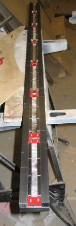
Here is one last picture. This one is the completed ribbon. All I have left to do now is wind another transformer and attach two lengths of "T" shaped aluminum that will serve as the mounting brackets. I should be able to easily complete it tomorrow.
Attachments
I finished the mounting brackets and the second transformer. I mounted the new speaker on the old test stand and listened to it. It sounds good – about the same as the first speaker. I've made no measurements yet of the new speaker and mounting method.
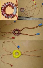
I've included some pictures showing the steps in building the transformer. It's the same design as the first:
Primary = 18 awg, 17 turns, 3 wire series multifilar winding (equivalent to 51 single wire turns)
Secondary = 24awg, 9 turns, 12 wire parallel mulitifilar.
The top left picture shows the primary with the three wires per turn.
The top right picture shows how the three wires are connected to get them series connected. Note that it's a good idea to mark each end of the three wires to make it easier to figure out what to connect.
The third picture shows the secondary wound on top of the primary. No need to keep track of individual secondary wires since they are all wired in parallel.
The last picture shows the completed transformer wrapped in electrical tape to keep the windings tight to the core.
This probably my last post for a while, until I get my line arrays built and can listen to everything put together.
Attachments
Denis
this is one awesome thread,
although I don't know anything at all about ribbons, this has inspired me to read up more about the concept.
Will be following this thread and attempt to make one if you ever decided to make a diy page for us.
Simply awesome. 😱
this is one awesome thread,
although I don't know anything at all about ribbons, this has inspired me to read up more about the concept.
Will be following this thread and attempt to make one if you ever decided to make a diy page for us.
Simply awesome. 😱
Hi sqlev,
Thanks for the encouragement. It's always great to get positive feedback. Sometimes I have worried that my gory details may be too gory (e.g. does anyone really want five about transformer winding?).
I've started work on a web page but I'm still trying to get familiar with the tools and the mechanics of getting things set up. I should have a pretty good start on the web in a couple of weeks.
Regards,
Denis
Looks like a nearly complete DIY page already
Dear DHenryP,
Well, this looks to me as if it is a complete DIY page already. You have given us materials lists, where to get them, suggestions, how to assemble and some measurements. So easy I could do it ... maybe will. The only fly in the ointment is that last night, I just re-read Linkwitz's pages (and pages and pages), and understood a lot of it, and am now tempted to make an Orion instead.
But, maybe not an Orion, perhaps a diferent open baffle speaker design with a 3 foot true ribbon ... hmmm ... Interestingly his MT crossover point is exactly what you were thinking about for your system to be. I have to look at his prices again. I think that the price for plans for the Orion includes his "Analogue Signal Processor" crossover which is fully modifiable to any three-way ... I think, so even if I do not get on with the open-baffle speakers, I will have some nice drivers for mid- and woofer- and if I want, I could use your tweeters for another design.
Paralysis by analysis strikes again.
Regards,
George.
Mark Walsh.
Dear DHenryP,
Well, this looks to me as if it is a complete DIY page already. You have given us materials lists, where to get them, suggestions, how to assemble and some measurements. So easy I could do it ... maybe will. The only fly in the ointment is that last night, I just re-read Linkwitz's pages (and pages and pages), and understood a lot of it, and am now tempted to make an Orion instead.
But, maybe not an Orion, perhaps a diferent open baffle speaker design with a 3 foot true ribbon ... hmmm ...
Interestingly his MT crossover point is exactly what you were thinking about for your system to be. I have to look at his prices again. I think that the price for plans for the Orion includes his "Analogue Signal Processor" crossover which is fully modifiable to any three-way ... I think, so even if I do not get on with the open-baffle speakers, I will have some nice drivers for mid- and woofer- and if I want, I could use your tweeters for another design.Paralysis by analysis strikes again.
Regards,
George.
Mark Walsh.
Hi George,
I don't expect to be doing a whole lot original writing in my web page - mostly cut a paste from this thread. The disadvantage of depending on this thread is that some time in the future (months?), diyaudio will delete the pictures form their server. At that point folks reading the thread will see a lot of "As you can see in this picture..." but no pictures. The other advantage will be that I can compress and organize the information so someone just starting does not have to paw through 15 pages of posts.
I've got my page started and have actually posted a couple pages online. It should not take too much longer to complete it and clean it up so I can advertise the address.
Good luck with your "orions". I would have tried open baffle myself if I had the room.
Regards,
Denis
dhenryp said:The disadvantage of depending on this thread is that some time in the future (months?), diyaudio will delete the pictures form their server
Deletion of pictures in the database is not something we would do...
dave
planet10 said:
Deletion of pictures in the database is not something we would do...
dave
That's good to hear. I had just assumed that when I read an old thread and the pictures are gone that the forum had deleted them. I probably got confused between this and another forum.
dhenryp,
Your work is definitely appreciated. I don't have time to replicate your efforts currently, but I would definitely like to in the future. The level of detail you've provided is great!
Thanks!
Your work is definitely appreciated. I don't have time to replicate your efforts currently, but I would definitely like to in the future. The level of detail you've provided is great!
Thanks!
Hi Tiroth,
Thanks for the encouragement. I've been building up a web page. It's still not nearly complete but here it is in progress:
http://home.comcast.net/~hendentures/
When it's done, I'll post an update in this thread and add it to the DIY web page list on the loudspeaker forum.
I've also been working on the line array, where the ribbons will live. The array is still quite away from being complete but I have started cutting MDF. I have all the parts and supplies and I'm hoping to make some significant progress this weekend.
Regards,
Denis
Site looks excellent ...
Dear DHenryP,
I just popped by your DIY site and it looks excellent. Very professional but uncluttered appearance. Congratulations,
George.
Dear DHenryP,
I just popped by your DIY site and it looks excellent. Very professional but uncluttered appearance. Congratulations,
George.
dhenryp said:Hi Tiroth,
Thanks for the encouragement. I've been building up a web page. It's still not nearly complete but here it is in progress:
http://home.comcast.net/~hendentures/
When it's done, I'll post an update in this thread and add it to the DIY web page list on the loudspeaker forum.
I've also been working on the line array, where the ribbons will live. The array is still quite away from being complete but I have started cutting MDF. I have all the parts and supplies and I'm hoping to make some significant progress this weekend.
Regards,
Denis
Great site! Take a look at mine at:-
http://www.geocities.com/ec1288/
It featues diy audiophile projects include Genesis ribbon and NHT 1259 speaker, Audio Note Ongaku amp, Pass Labs Aleph 5 amp and Altec Lansing A5 VOTT speaker. Lots of free schematic diagrams, books and CD review.
- Home
- Loudspeakers
- Planars & Exotics
- Another DIY Ribbon thread