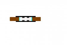
Hi ,here is a simmultion in femm 4.2.It dosen´t matter if polariety in the gabs are alike or reversed.
The dimensions are my idea´s ,if you want it i can make it from your dimensions

Fieldgab strength is app. 0.65 T.
The dimensions are my idea´s ,if you want it i can make it from your dimensions
Fieldgab strength is app. 0.65 T.
Thanks a lot
I already miss your fullrange planars, I really do 🙄
Well, I did try the FEMM again, but cant figure out the last bit 😡
Whats your opinion of this simulation
Very little field stray
But to me it also looks like the power stays in the iron, and not being very strong in the gap, shouldnt it at least be orange
Whats your experience when it looks like this
Wonder what would happen if there was a little airgap in the iron midpoint
Or maybe the gap should be at the other end, between the iron
But that would make constuction stability a bit difficult
Looking at below fig, yellow seems to be ok
Also, the little spread of the field, on each sides of the gap makes it possible to have 3 "strings" in each gap, with no need to have them on both sides of the diaphragm
Thanks again
Attachments

Hi again.
I cant tell, but it seems to be the draving thats wrong.
To me it seems that the iron is not sepperated in the middle, annyway here is my idea.

Fieldstrength is app. .55 T,i used ferite 10x20mm.
I have some ideas for the construction too.
I cant tell, but it seems to be the draving thats wrong.
To me it seems that the iron is not sepperated in the middle, annyway here is my idea.
Fieldstrength is app. .55 T,i used ferite 10x20mm.
I have some ideas for the construction too.
båndsei said:
I have some ideas for the construction too.
Thanks fore sim
Doesnt look better than original
But I also just got an idea to a change
I will make a drawing
My concern is also to achieve easy assembling, and maybe even less diffraction
Lets see where it goes 🙂
Which steel or iron is being used in these FEMM simulations?
Which magnets? (NdFeB40 ?)
Also, a FEMM question: How do you get FEMM to show that pop-up giving flux denisty at a particular point like that?
(I keep having to try and figure out "is this point mostly yellowish or orangish or greenish?" Not very precise at all.)
Which magnets? (NdFeB40 ?)
Also, a FEMM question: How do you get FEMM to show that pop-up giving flux denisty at a particular point like that?
(I keep having to try and figure out "is this point mostly yellowish or orangish or greenish?" Not very precise at all.)
tinitus said:This might be the final version
Its easier to build/assemble, but still a tricky challenge
May need a small ribbon placed on top(10khz)
Hello ,
This looks like what i also had in mind for doing a Push/Pull ..........
Maybe we should arrange a group trip to Bandsei 😀
Here is a lager picture.

I have used ferite magnets .In the gab there is 0.55T!!
That`s quite good .If you use Neodymn.,you would get app. 1,0 T
It`s a good result.
You got too have some distance betwin the iron or the field crosses the air .

My idea is to assemble it all, and then slide the membrane thrugh
the gabs. The membrane should be tied with 2 vertical wires, and several ones horisontally,theese can go thrugh the gabs betwine the magnets.
Neededandwanted.
On my example you se in the window (B) 0,55T thets from the gab.
In the toolbox choose dot/point and plave the arrow where you want to "read" and clik.
I have used ferite magnets .In the gab there is 0.55T!!
That`s quite good .If you use Neodymn.,you would get app. 1,0 T
It`s a good result.
You got too have some distance betwin the iron or the field crosses the air .
My idea is to assemble it all, and then slide the membrane thrugh
the gabs. The membrane should be tied with 2 vertical wires, and several ones horisontally,theese can go thrugh the gabs betwine the magnets.
Neededandwanted.
On my example you se in the window (B) 0,55T thets from the gab.
In the toolbox choose dot/point and plave the arrow where you want to "read" and clik.
båndsei said:In the toolbox choose dot/point and place the arrow where you want to "read" and click.
That's what I was trying to do and it never worked.
For me the problem was solved by going to the View menu and checking "Output Window." Then it was all working fine.
A.Wayne.
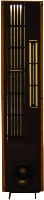
The first one, i build and the last one.Look in curved magnetostatic speaker,there is a picture of the last one.
The first one, i build and the last one.Look in curved magnetostatic speaker,there is a picture of the last one.
Bandsei ,
Could you describe it a bit for me ?
From the pics it looks planer magnetic . Are you saying it also has ribbon drivers ? are you using neo's?
regards,
Could you describe it a bit for me ?
From the pics it looks planer magnetic . Are you saying it also has ribbon drivers ? are you using neo's?
regards,
Here is a close up.

It is planar and ribbon on the same "frame"
I use neos 10x6x70mm.
I think this belongs to the tread:curved magnetic speaker.
It is planar and ribbon on the same "frame"
I use neos 10x6x70mm.
I think this belongs to the tread:curved magnetic speaker.
båndsei said:
My idea is to assemble it all, and then slide the membrane thrugh
the gabs.
Its a good idea, which would make assembling much easier
I had the same thought, but couldnt solve it, so I left it
But also realised the risk of diaphragm dammage if not
After working some more with the idea I think I have found a way to do it
Its all bolted together
Diaphragm is slided in from top or bottom
Also thought of a way to make fine adjustment between diaphragm and magnets
Attachments
tinitus, I may be viewing it incorrectly, but that last picture reminds me a lot of the Carver/Bohlender Graebener RD series "ribbons."
http://www.parts-express.com/pdf/264-710.pdf
or all of the BG's
And since the BG's are still made to this day using ceramic-8 magnets, I wonder if doing a Neo52 version might be slick - or at least a lot more sensitive/efficient.
Two wide aluminum traces on Kapton film and 3 columns of skinny Neo's stuck to stamped steel pieces front and back.
BG sells them for about $130 USD per vertical foot.
Eminent Technology sells a push-pull planar magnetic speaker that has robust construction and gets good reviews. ET builds both a push-pull planar midrange and tweeter. The picture shows the heavy steel frame.
The best Apogee midbass planars used adjustable "real springs' attached to a wooden frame that clamped the Kapton film along the entire edge. This allowed Apogee to tune the trapezoid shaped film to different frequencies along the length to remove major resonances. Springs and kapton are very stable over decades of use. Apogee used a "push only" single magnet motor construction, claiming that a non-obstructed front wave launch was critical, and the large panel had very low X-max and hence low distortion.
With today's NdFeB supermagnets, I favor separate true ribbon midrange and tweeter linesources, and a line array of standard speakers for bass.
http://www.eminent-tech.com/
Attachments
Hello ,
The Idea is to use push/pull for bass /midbass only !
The ET panels are 2 small and would not work here and would be a hindrance in frequencies above 800 hz.
Tinitus;
I would have driver membrane mounted to it's own frame tensioned accordingly and then slide the membrane between the assembled unit .
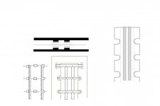
Hi Tinitus.I think we have made a mistake. In my magnetgab and yours with the magnets mounted across eachother ,the membrane will try to move sideways instead of back and furth.
Pardon my English.
In your model it can be done in another way.Like This

And "my" gab like the other
Pardon my English.
In your model it can be done in another way.Like This
And "my" gab like the other
In that most recent picture, why are the magnets staggered like that? I don't think that design will work.
The standard arrangement for a push-pull planar magnetic is like this:

You are definitely right about the ribbons moving sideways in the earlier design. A current carrying conductor will move across lines of flux, not parallel to them.
The standard arrangement for a push-pull planar magnetic is like this:
You are definitely right about the ribbons moving sideways in the earlier design. A current carrying conductor will move across lines of flux, not parallel to them.
You are absolutely right
Its very poor that I didnt see it, and presented it without thinking it through properly
And I actually know the "trick"....magnet pole pointing into palm of hand, fingers in signal direction, and "source" will move in direction of the thumb(or something like it)
Thankyou
It would work better with a "Rumanoid" design
As mentioned, the frontmounted magnet are really a compromise, as is the frontgrille of most commercial planars
But I will only do it if I think it will be better than any commercial available
There is one specific reason why I begin to doubt the sense of pushpull magnets
One is that there now seems to be very little gain in field strength, despite the gained better linear diaphragm movemet
Anyway, as I see it there should really be as little diaphragm movement as ever possible
And everything possible should be done to free the planar of moving much
Fore that very reason I wont use it below 100hz, or maybe even cross it higher
Though the nice fullrange character of "bandsei" design really did give me high hopes
Whether the curved design has a say in this is unknown, and one can only speculate
Fore that reason I think I will leave the pushpull design alone
I fear the drawbacks are worse than whats gained
I will now focus on a planar with "FULLRANGE" character, to be used maybe 150-10khz
It may even be possible to have the diaphragm much closer to backmounted magnets instead
And a small true ribbon placed on top
Thanks again fore correcting this, before gotting out of hand
New project, or should I say, stick to the old
Or RUMANOID 😎
Though I thought the advantage of the rumanoid was tighter magnet gap, its also clear now that it can move a hell lot more, with no "touching" of magnets
Good luck guys 🙁
- Home
- Loudspeakers
- Planars & Exotics
- Another DIY Ribbon thread