a.wayne said:
Yes very similar to what i had in mind ...🙂 ............except for the woofer tower
Yeah, woofer array was just fore looks 😀
I have been working on the idea
And done some cost calculations, and Im afraid neo magnets gets quite expencive
On the other hand, if it works it will be very hard to beat
I have magnets fore some small ribbons, though they will need transformers
To me, fore this to make sense, it should be done with no transformers, so only bigger will do
Still, I fear some difficulties in assembling such pushpull planar units
Magnets are very strong, and I have experienced that they could bent a 3x20mm metal bar...sidewards

Though, due to the push-pull the magnets may not need to be so big(thick)
Also, the design I have worked on here, uses a "not loaded" part of the diaphragm as the active part, and you could almost call it an Linesource-Manger
There may be ressonance issues
But it may depend a lot on diaphragm material...some use very thin "Japan-paper"...you know, like the paper used fore model airplanes
Its really tempting to try and do it 😎
Attachments

Yes, I also figure about 10mm gap
Delrin bars instead of metal might make it much easier to assemble
Though, metal bars is part of the magnet system, but may not be important...so your right that it could work ok without the metal "pole"connection
Dont know how to simulate this thing 😡
http://femm.foster-miller.net/wiki/HomePage
Delrin bars instead of metal might make it much easier to assemble
Though, metal bars is part of the magnet system, but may not be important...so your right that it could work ok without the metal "pole"connection
Dont know how to simulate this thing 😡
http://femm.foster-miller.net/wiki/HomePage
No, use the delrin bars as spacers , of course the magnets will have to be on metal bars or you will have a weak field ..
The delrin will be between the bars and join both push pull sections together with a 10 mm gap....
I have downloaded the Femm software and do not find it intuitive and have not yet made the effort to understand or become familiar with it .
Regards,
The delrin will be between the bars and join both push pull sections together with a 10 mm gap....
I have downloaded the Femm software and do not find it intuitive and have not yet made the effort to understand or become familiar with it .
Regards,
a.wayne said:No, use the delrin bars as spacers , of course the magnets will have to be on metal bars or you will have a weak field ..
Regards,
Thank you, but I did understand what you meant
But my plan was to use a 6mm metal PLATE, and cut holes making the needed "pattern", shown on drawing
It will ofcourse be much easier to do it the ordinary way with seperate bars, like you suggest...mounting would be easier too, and less risky, handling a smaller amount of magnets
I like the idea of doing each section as a complete unit, but I guess its simply too difficult to handle
Would be much easier if assembling could be done before magnetising
Attachments
Hi there
Here is an other idea:

If the space betwin the membranes is air tight and the membranes are connected so that they move in the same direction ,will it be "push-pull"??.
Here is an other idea:
If the space betwin the membranes is air tight and the membranes are connected so that they move in the same direction ,will it be "push-pull"??.
Its a variation of this, and I have considered exactly what you suggest
http://home.tele2.fr/mon-site-perso/
Advantage is very strong gap
But very complicated construction
Also mechanical unstable
Bars holding the magnets will have to be VERY strong as they will be drawn towards each other...and you cannot mount spacing because thats where the "coil-foil" is placed
I have had ordinary magnet mounted on iron 3x20mm, and metal bars bent sidewards over the 20mm clatching together like it was nothing
A tweeter would be easier to handle
Pushpull its not, but more like the ordinay though with double membrane, which is much heavier
Though, as said you can make a have a VERY strong gap
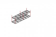
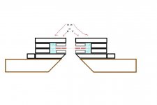
I may have solved some of he difficulties fore assembling my planars, so that magnets doesnt take control over the process
You see the 2 halfs ready to be joined together
Red lines are threaded rods
Looking at picture, there are threads fore the rods in the "top" section, and the rods are standing against the "bottom" section, so that they dont clash together
Bit by bit I may be able to put them together by turning the threaded rods
During "assembling" I may also use a MDF box to control any sidewards movement
I think its possible
Attachments
Think about doing half circular "cuts" along the sides of diaphragm, changing the ressonance issues, but in what way I dont know
When I looked at it, I was reminded of Thiel/Accuton 🙄
Beginning to think that it may be best to just do a tweeter/mid planar, and let the rest be done by ordinary woofers as I think they will be needed anyway
When I looked at it, I was reminded of Thiel/Accuton 🙄
Beginning to think that it may be best to just do a tweeter/mid planar, and let the rest be done by ordinary woofers as I think they will be needed anyway
Attachments
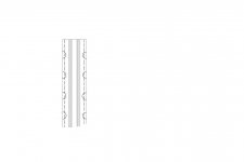
It is not that easy to explain my idea.
But it is a simple construktion,here is shown a "cut" thrugh the middle,the idea is to use the magnetic field iv both sides of the magnet

But it is a simple construktion,here is shown a "cut" thrugh the middle,the idea is to use the magnetic field iv both sides of the magnet
With these soft and flexible diaphragms I dont think the pushpull you describe will have any advantage
It may be p-p alright, but I dont think the 2 diaphragms are coupled tightly enough to work as a unit
Reminds me that "HifiKlubben" once sold a cheating OB
It was an ordinary big woofer, with a big passive plastic film diaphragm in front
Tweeter ribbon was genuine
it actually worked
It may be p-p alright, but I dont think the 2 diaphragms are coupled tightly enough to work as a unit
Reminds me that "HifiKlubben" once sold a cheating OB
It was an ordinary big woofer, with a big passive plastic film diaphragm in front
Tweeter ribbon was genuine
it actually worked
hi båndsei
I have made a drawing to try and understand you suggestion
Theres one single huge advantage of having two opposite diaphragms
Its possible to get a higher impedance, or making it smaller and still maintain high impedance
It also means that the two sides have opposite polarity, which can be used to make nice short connections
Im afraid that apart from that there are only drawbacks
You still have the ordinary weak magnet field, and unfortunately at high SPL it seems like the diaphragm really likes to get out of the field, and not returning 😡 sounds crazy, but I have seen it many times
Push-pull PLANAR means something special
Its two MAGNETSYSTEMS working together, with a much more powerful and linear magnet field
Well, it is that with ordinary woofers too, but unfortunately theres also two cones
PLANARS are really ideal on this point, cause the two magnetsystems are working the very same diaphragm
Backside is the magnets in front of the diaphragm, and it might not be too good further up in frequency
wow, I just got a crazy idea to a dynamic real pushpull sub driver...magnets on both sides of the cone...patent pendable 😀
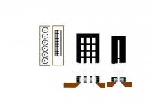
Push pull planer for bass , midbass. 😀
Standard ribbon midrange -high frequencies..........................
Standard ribbon midrange -high frequencies..........................
a.wayne said:
Standard ribbon midrange -high frequencies..........................
Maybe 😀
With N45-52 neos and pushpull...might result in very good sensitivity 😉
And the one I show could have reversed polarity, to make cable connections short
Found a nice one at Applied Magnets
http://www.magnet4less.com/product_info.php?cPath=1_5&products_id=673
Expencive, but theres a N42 with same size, which is pretty nice too
And its heavy, so costly shipping too
Hard to imagine the power of such a magnet gap
The N52 pulls 20kilo, and the N42 pulls 15kilo
Also, with foil on both sides of diaphragm theres lots of "signal" positioned in the gap, which is very good fore efficiensy
But I might talk to a danish company about magnets without nikkel plating, which I would expect to better...direct contact between magnets and poles, and might be cheaper too
🙂
Attachments
Hello,
try to simulate it using FEMM or equivalent FE software before prototyping.
Regards, Timo
try to simulate it using FEMM or equivalent FE software before prototyping.
Regards, Timo
I wish I could 
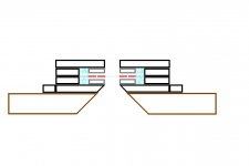
But sure, I would like to know what difference it makes if I reverse polarity on "left/rigt" magnetsystem in the planar I show
Reversed with N-S would be convenient, so that connections will be nice short and easy, right
I suppose the N - N configuration will look better on sims, but question is HOW much worse "field-stray" there would be with a N - S
Please note that it consists of two independant magnetsystems, one on each side of visible diaphragm
And I do know that theres a lot of diffraction issues with this design, but sensitivity and control is first priority
Any suggestion to the field stray issue ?
Attachments
tinitus said:
I suppose the N - N configuration will look better on sims
Dont know why thought that

The desired "N - S", left to right, logically appear to be the better one, in terms of "field-stray"...longer path, if it matter at all
But no doubt, field-stray there will be, which could be the achilles heel of this 🙄
Sorry guys, Im confused and posting too much, and confusing you as well
But it seem my head is spinning
Ofcourse I was right in the first place
The one with "reversed" polarity N - S, which I want, really is the one that may have the worst stray-field issues...what else
But probably nothing much to worry about
But it seem my head is spinning
Ofcourse I was right in the first place
The one with "reversed" polarity N - S, which I want, really is the one that may have the worst stray-field issues...what else
But probably nothing much to worry about
Go with the Nickel Plating!
Hi Tinnitus
The neodimium magnets rust very quickly if they are not plated. So some type of coating is really a good idea.
Even the nickel can have problems if there are chips on the magnet. I have a couple beside me that are all starting to rust because I played around with them to much over the years.
Mark
Re: Go with the Nickel Plating!
Hi My danish mate "båndsei" just told me the same
But thanks anyway, its valuable information
Just visited "båndsei" and heard his designs
He has quite a lot actually
And they definately have fine qualities that are worth working with
Got a few tips fore making diaphragms, and quite easy really
Much lighter and better than what I did in my past
Very positive and definately worth the effort and money
Now Im 110% sure, thats the way
But no doubt that bass has to go somewhere else 😀
I am told that higher "N" grade are more fragile, where i thought the opposite, that lower grade neos are most fragile I have broken too many already, but they may have been of low quality
mwmkravchenko said:Hi Tinnitus
The neodimium magnets rust very quickly if they are not plated.
Mark
Hi My danish mate "båndsei" just told me the same
But thanks anyway, its valuable information
Just visited "båndsei" and heard his designs
He has quite a lot actually
And they definately have fine qualities that are worth working with
Got a few tips fore making diaphragms, and quite easy really
Much lighter and better than what I did in my past
Very positive and definately worth the effort and money
Now Im 110% sure, thats the way
But no doubt that bass has to go somewhere else 😀
I am told that higher "N" grade are more fragile, where i thought the opposite, that lower grade neos are most fragile
I have broken too many already, but they may have been of low quality- Home
- Loudspeakers
- Planars & Exotics
- Another DIY Ribbon thread