The output gets fed to the plate and comes out from the cathode attenuated mu-times lower.
The difference is that my input signal goes to the non-inverting pin.
That's actually a dumb thing to do. The relationship between anode voltage and anode current in a triode is non linear. So the feedback is non-linear. If the gain block is another triode it can be arranged that the distorted feedback cancels out the distortion in the gain block, instead of merely reducing it as neg feedback normally does. You can also do something similar if the gain block consists of a low distortion output stages eg ultra-linear driven by a triode gain stage and a concertina phase splitter. In this case the distortion from the triode gain block dominates, especially if the output tubes are not worked hard.
But that is not what you have in your circuit. Your gain block is not a simple triode. It's an op-amp driving a push pull pair. In your circuit, the neg feedback via the triode will make the system distortion worse.
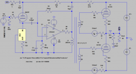
Below is the more conventional inverted Futterman OTL. I dislike this version for few reasons:
1. The need for another higher supply +350V
2. Heater power elevation for the cathodyne is required
3. Since 6C33C varies wildly between each tubes, matched pair are very unlikely found and DC servo is needed to keep the output offset minimum. Hence another need for bipolar supply for DC servo op-amp.
Your circuit, according to your posts, must operate in Class B. You have transformer coupled the driver to the output stage as is normally required for Class B. But you have ruined it by inserting 220 nF capacitors. You are going to have big problems with grid blocking. To get full output (in fact anything much more than a watt) the grids have to be driven positive and will draw grid current, charging up the grid capacitors. The result will be really bad distortion.
The "Flutterman" circuit you posted has the same problem.
In Class B, the grid needs a low impedance DC return to the cathode. This is done by inserting the grid bias voltage supply in series with the transformer secondary, so no grid capacitor is needed.
Still, some people like a bit of distortion. Not as much as this amp will produce though.
Last edited:
Keit--Ridiculous...? Nah, not at all......
--Did you know--Mullard valves were only guaranteed for three months from date of purchase in 50's and 60's....Even says as much on some of the boxes the valves came in!
When a TV set/radio was purchased, often the valves were not covered by a year's guarantee, although the CRT may have been by some makers.....
Well aware how many valves were used in early colour sets as I used to repair 'em in those days, G6 had 21 valves for instance, and on average after a year would fail, then approx every year after repairs It was just parr for the course in those days.....
Housewives Never left sets on all day--There was NOTHING but test-card F to watch in those days, Programming started around 3.30 in afternoon--So THAT comment is ridiculous!
(Only other programming that was transmitted, were 'For Schools' shows, and you would have to have been severely Bored to watch those for the couple of hours on the mornings)
A replacement guarantee is different to a ratings guarantee you seem to have in mind it seems. Well known that vacuum tubes can last a long time, There was a AC/HL in some rack of the BBC that had been in a basement in constant service for 60 odd years and was still operational, and was within spec. This however, is a signal triode not subject to the stresses power types are.
Any power-valve that after 1000 hours that is Guaranteed to perform to full data-sheet ratings is just that. Guaranteed.
Western Makers of consumer-valves did NOT guarantee that their valves would comply with the full data-sheet ratings after 1000 hours.
--Doesn't mean to say that the valve would not be serviceable after that time of use does it, may still perform perfectly well in the circuit its in, but may well fail if tested against the full data-sheet ratings!
How many ordinary Lightbulbs claim 1000 hour use (Not Guarantee) on the package and only last a few hundred...? We've all seen 'em
Answer,--Lots! (Seem to be plagued by 'em, no matter What make, some fail on turn-on, but most just pop during use....)
To get full output (in fact anything much more than a watt) the grids have to be driven positive and will draw grid current, charging up the grid capacitors.
It appears to me that you can go well into AB operation without drawing grid current. Just not AB2 where indeed you'll see blocking. I'd be interesting in seeing measurements of the circuit in question- the Futtermans actually measured pretty well (except for high source impedance). Their Achilles heel was reliability, runaway oscillation being a common problem.
The AB approach by Ralph Karsten using a circlotron seems to be quite a bit better in that respect.
It appears to me that you can go well into AB operation without drawing grid current. Just not AB2 where indeed you'll see blocking.
You only need to look at the grid tube curves to see that Class B necessarily draws grid current.
Yes, you can go well into AB operation without grid current. But AB operation in the OP's example starts at around 1 watt. He expects 25 watts. That won't be AB. it will be Class B with LOTS of crossover distortion.
--Did you know--Mullard valves were only guaranteed for three months from date of purchase in 50's and 60's....Even says as much on some of the boxes the valves came in!
Guarantees are a marketing exercise. Guarantees vary from country to country as markets required. Even though many parts were imported from teh same factories. The engineered service life is generally well beyond the retail guarantee.
One of the curious things that happened in my country: Philips made sets here under three brands in three factories: Philips, Astor, and Pye. They all used mostly Philips/Mullard parts (some tubes from AWV, transformers from Rola, Ferguson and A&R, speakers from Rola or MSP (AWA). They marketted Philips-banded sets as a higher priced premium brand. There was also Kriesler, who had a cooperative agreement with Philips and used the same parts in very similar designs. The marketing worked too well - in the 1970's when affluence increased, sales of Pye fell right off. So instead of the usuall 12 month guarantee (normal in Australia for just about anything), they started offering 3-year guarantees on Pye sets to balance it up. That makes no sense at all from an engineering point of view but some sense from a marketing point of view.
Incidentally, common faults in Philips sets in the first few years were dry joints. They used an early automated soldering system, when other brands except Kriesler were still using hand-soldering. Kriesler did much better on soldering for some reason.
Well aware how many valves were used in early colour sets as I used to repair 'em in those days, G6 had 21 valves for instance, and on average after a year would fail, then approx every year after repairs It was just parr for the course in those days.....
Well, even one tube failure about each year is 12 x better than the spec for the 6C33C.
Maybe in your country when there was only one channel of the government BBC. Not in my country, where there was 2 or 3 commercial channels (depended on location) to chose from as well as the ABC. And in other countries. Programming usually started at 9:00 AM in the early days and soon went to 24/7 programming. Some of the biggest advertising revenue comes in the "housewife" hours during the day - "We have a fantastic deal - this week only, exclusive to Channel 7 viewers, get this (wierd looking) multipurpose cleaning device for only $199.95 and we'll throw in this extra thing absolutely FREE! Ring now - operates are standing by!"Housewives Never left sets on all day--There was NOTHING but test-card F to watch in those days, Programming started around 3.30 in afternoon--
Western consumer tubes were engineered to give about a 20,000 hours service life within specs.
How many ordinary Lightbulbs claim 1000 hour use (Not Guarantee) on the package and only last a few hundred...? We've all seen 'em
Answer,--Lots! (Seem to be plagued by 'em, no matter What make, some fail on turn-on, but most just pop during use....)
Light globes are a diffrent thing. They are made with much finer wire run much hotter - at least 2000K, not the 1100 K that tube heaters run at.
And light globes, when made in western countries, did actually last as long as they were supposed to. But now they come from China and Indonesia, and they are a lot worse.
Last edited:

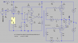
Here are modifications based on feedback, it works, please take a look and input more mods as needed.
We can't conclude that yet based on your mods as the transformer model is still too perfect. You need to put the winding resistance, leakage inductance, interwinding capacitance, etc.
What's that 1 ohm resistor in the output ogf the op-amp supposed to do?
It's not enough to prevent the op-amp from driving a large DC current into the transformer. It's too low to cure an instability issue.
Why have you added C4? It means the output stage has positive feedback around it (hence oscillation), and it will overload the op-amp.
It's not enough to prevent the op-amp from driving a large DC current into the transformer. It's too low to cure an instability issue.
Why have you added C4? It means the output stage has positive feedback around it (hence oscillation), and it will overload the op-amp.
That's actually a dumb thing to do. The relationship between anode voltage and anode current in a triode is non linear. So the feedback is non-linear. If the gain block is another triode it can be arranged that the distorted feedback cancels out the distortion in the gain block, instead of merely reducing it as neg feedback normally does. You can also do something similar if the gain block consists of a low distortion output stages eg ultra-linear driven by a triode gain stage and a concertina phase splitter. In this case the distortion from the triode gain block dominates, especially if the output tubes are not worked hard.
Some would say dumb, some would say smart.
http://www.diyaudio.com/forums/tubes-valves/20686-se-sound-p-p-amplifier.html
Of course, we do it anyways. If you want very low distortion, SS amps get you well below 0.00xx% at much more output power than tube amps get you.
But that is not what you have in your circuit. Your gain block is not a simple triode. It's an op-amp driving a push pull pair. In your circuit, the neg feedback via the triode will make the system distortion worse.
That is actually the point.
Your circuit, according to your posts, must operate in Class B. You have transformer coupled the driver to the output stage as is normally required for Class B. But you have ruined it by inserting 220 nF capacitors. You are going to have big problems with grid blocking. To get full output (in fact anything much more than a watt) the grids have to be driven positive and will draw grid current, charging up the grid capacitors. The result will be really bad distortion.
Mine remains in AB1 all the way to 16W, no grid current here. That Futterman works in AB1 also, believe it or not. Ask Alastair E, he built one. Here's the grid voltage (green) compared to the cathode voltage (blue) of the upper triode. Green never gets above blue, so no grid current.
An externally hosted image should be here but it was not working when we last tested it.
More proof, here's the current flowing on each of the 0.5R cathode resistor on the output tubes. That sure looks like Class AB to me.
An externally hosted image should be here but it was not working when we last tested it.
I'd be interesting in seeing measurements of the circuit in question- the Futtermans actually measured pretty well (except for high source impedance).
Hi SY,
I hope this is what you're asking for.
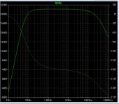
My version simulates THD 0.758882% at 16W, below is the profile.
An externally hosted image should be here but it was not working when we last tested it.
But this is of course useless as the transformer model is not adjusted yet.
The Inverted Futterman simulates THD of 2.549545% with following profile.
An externally hosted image should be here but it was not working when we last tested it.
The opamp provides a virtual ground, acting as an I to V converter. The actual AC voltage at the input is essentially zero. Remember, in the limit of infinite gain, the two input terminals of the opamp must be at the same potential. So the CCS doesn't change that, it just means that current variations through the tube are translated (more or less) exactly into current variations into the virtual ground, which are then translated exactly into voltage variations at the opamp output. The feedback resistor determines the transformation ratio of amps to volts.
Ah i see now. Now the question, apart from phase differences, is there any other differences especially regarding to distortion profiles between my feedback and John's? I will have to simulate it to see.
What's that 1 ohm resistor in the output ogf the op-amp supposed to do?
It's not enough to prevent the op-amp from driving a large DC current into the transformer. It's too low to cure an instability issue.
Why have you added C4? It means the output stage has positive feedback around it (hence oscillation), and it will overload the op-amp.
Thank you for feedback.
I have made another change about the inserted capacitor in sec winding of inter-stage trans you mentioned earlier, I can get rid of, not sure it's all very safe. You need DC path in drive for AB1 (draw grid current) to happen, now the output level has increased somewhat.
The output of OpAmp is supposed to AC tied to the tube anode isn't? They are same phase, no oscillation.
The 0.1hm resistor help to prevent back emf into the system I think, optimum value yet to be determined.
Attachments
won't this circuit melt down the plates at any sustained current over 1 amp assuming a low < 20 ma bias?
60 w plate dissipation x2 less then 142v * 1A
By my estimation you need 4 more pairs of 6C33C's and B+ of 100v
60 w plate dissipation x2 less then 142v * 1A
By my estimation you need 4 more pairs of 6C33C's and B+ of 100v
Keit pointed out this earlier:
"No, because they are feeding loudspeakers. A loudspeaker has a DC resistance about the same as its rated impedance. In the 1950's, when spekaers were more efficient, a typical 8 ohm speaker had a DC resistance of around 6.4 ohms. Today's speakers are built for better sound quality and not efficiency. Their DC resistance is closer to the nominal impedance.
But you are taking the output of an op amp direct into a transformer winding, in which we can expect a vary low DC resistance, so a much greater DC current."
I have inserted a resistor of 20 ohms to compensate for low DCR of this inter-stage transformer. It appears to work well when I try to reconfigure the inductance, it does make better sense now than before. Or you can insert DCR directly into the inductor.
Also the OpAmp output is tied to tube anode via a 1K resistor, somewhat isolated it from global NFB, you can test by change the load resistor from 8 ohms to 80 ohms, the output should be constant.
Any other comments are welcomed.
Attachments
Last edited:
Oh, I see. You WANT distortion. LOTS of distortion it seems.That is actually the point.
There is a world of difference between the quite low and quite benign distortion of a simple SE triode output and the large distortion from your more complex circuit.
Mine remains in AB1 all the way to 16W, no grid current here.
Your simulation graphs clearly show Class B operation - each tube is cut-off for approx half the cycle - that's the definition of Class B. See the cathode current curves flat along the zero amp baseline? Class B.
Your simulation graphs also clearly show that the grids are driven positive WELL into the grid current region. You have a grid bias of 47 V and a grid drive of 122 V pk-pk. For AB operation the grid excursion must be less than twice the bias.
It will be much worse in practice. In any case even 2.5% is pretty disgusting. In choral works you'll barely be able to make out the words.The Inverted Futterman simulates THD of 2.549545% with following profile.
Remember what I said about newbies trusting their SPICE simulations? Like Yer 2 school kids trusting their fumble fingered use of a calculator.
The op-amp is in inverting mode. So if global feedback is negative at teh op-amp input, it is positive at the transformer. It's not teh op-amp that will oscillate, it's the output stage.The output of OpAmp is supposed to AC tied to the tube anode isn't? They are same phase, no oscillation.
The 0.1hm resistor help to prevent back emf into the system I think, optimum value yet to be determined.
It won't do that. The output impedance of an op-amp is very low, and even lower with local feedback - you'll get no back EMF in any case (assuming the output stage doesn't oscillate - and if it does the resistor is not going to save the op-map then)
A couple small changes to eliminate the extra poles and enforce a maximum reflected impedance. Apparently I don't have the symbols for the chipamp and 317.
Seems my earlier post was ignored/overlooked. You must enforce a maximum reflected impedance, trying to reflect basically infinite impedance up until grid current where it will drop suddenly will cause issues with distortion and stability. It will work fine in spice, not in the real world.
Hi Keit,
I see we have clear fundamental difference here. I am sure my schematic and Futterman's are both class AB1 amplifier while you are clearly saying that they are Class B. From my point of view, there are three possible causes for this:
1. I am wrong and i don't know that i am
2. You are wrong and you don't know that you are
3. You are deliberately posting wrong facts (although you know they are wrong) out of some twisted ways you believe are effective to teach newbies by re-questioning their knowledge although that knowledge is clearly correct.
The solution to number 1 or 2 is to have a third party to state which one of us is wrong.. hoping that third party knows what he/she is talking about.
If it is number 3, well i personally say that is a dangerous thing to do. I am not sure if the mods would even allow it.
If indeed the case here is number 1, i preemptively apologize to you and humbly thank you for correcting me. From your posts, I believe i am much younger than you and i respect you.
Okay, now.. let's state the difference between amplifier classes:
Class A = both active devices remain conducting for the full output signal
Class B = each active devices ONLY conducts for each half part of the output signal, this means there will be no part of the signal where each device are both conducting at the same time. Clearly this will give you bad crossover distortion.
Class AB = both active devices remain conducting for only a part of the output signal, around the crossover region after which one of the device would cease to conduct and lets the other one take full charge of carrying the output signal. This means if we keep the output signal small enough to stay within the conduction limits of each device, we are staying in class A.
The main difference between class B and AB is the bias current. Active devices of the class B are biased at exactly 0mA. Anything higher than 0mA, we are going to class AB. My amp are biasing the output tubes at 200mA. This means if we keep the output power less than 160mW (where the current flowing through the load is less than 200mA), the amp runs in class A. Anything higher than that, it's class AB. My amp and the Futterman are simply not class B because the output devices are biased more than 0mA.
In the words of our holy Wikipedia, here is class AB:
Here it is explained by my previous graph.
Also, here is the other chart showing clearly there is no positive grid voltage with respect to the cathode.
I see we have clear fundamental difference here. I am sure my schematic and Futterman's are both class AB1 amplifier while you are clearly saying that they are Class B. From my point of view, there are three possible causes for this:
1. I am wrong and i don't know that i am
2. You are wrong and you don't know that you are
3. You are deliberately posting wrong facts (although you know they are wrong) out of some twisted ways you believe are effective to teach newbies by re-questioning their knowledge although that knowledge is clearly correct.
The solution to number 1 or 2 is to have a third party to state which one of us is wrong.. hoping that third party knows what he/she is talking about.
If it is number 3, well i personally say that is a dangerous thing to do. I am not sure if the mods would even allow it.
If indeed the case here is number 1, i preemptively apologize to you and humbly thank you for correcting me. From your posts, I believe i am much younger than you and i respect you.
Okay, now.. let's state the difference between amplifier classes:
Class A = both active devices remain conducting for the full output signal
Class B = each active devices ONLY conducts for each half part of the output signal, this means there will be no part of the signal where each device are both conducting at the same time. Clearly this will give you bad crossover distortion.
Class AB = both active devices remain conducting for only a part of the output signal, around the crossover region after which one of the device would cease to conduct and lets the other one take full charge of carrying the output signal. This means if we keep the output signal small enough to stay within the conduction limits of each device, we are staying in class A.
The main difference between class B and AB is the bias current. Active devices of the class B are biased at exactly 0mA. Anything higher than 0mA, we are going to class AB. My amp are biasing the output tubes at 200mA. This means if we keep the output power less than 160mW (where the current flowing through the load is less than 200mA), the amp runs in class A. Anything higher than that, it's class AB. My amp and the Futterman are simply not class B because the output devices are biased more than 0mA.
In the words of our holy Wikipedia, here is class AB:
Class AB is widely considered a good compromise for amplifiers, since much of the time the music signal is quiet enough that the signal stays in the "class A" region, where it is amplified with good fidelity, and by definition if passing out of this region, is large enough that the distortion products typical of class B are relatively small. The crossover distortion can be reduced further by using negative feedback.
In class-AB operation, each device operates the same way as in class B over half the waveform, but also conducts a small amount on the other half. As a result, the region where both devices simultaneously are nearly off (the "dead zone") is reduced. The result is that when the waveforms from the two devices are combined, the crossover is greatly minimised or eliminated altogether. The exact choice of quiescent current (the standing current through both devices when there is no signal) makes a large difference to the level of distortion (and to the risk of thermal runaway, that may damage the devices). Often, bias voltage applied to set this quiescent current must be adjusted with the temperature of the output transistors. (For example, in the circuit at the beginning of the article, the diodes would be mounted physically close to the output transistors, and specified to have a matched temperature coefficient.) Another approach (often used with thermally tracking bias voltages) is to include small value resistors in series with the emitters.
Class AB sacrifices some efficiency over class B in favor of linearity, thus is less efficient (below 78.5% for full-amplitude sinewaves in transistor amplifiers, typically; much less is common in class-AB vacuum-tube amplifiers). It is typically much more efficient than class A.
Sometimes a numeral is added for vacuum-tube stages. If grid current is not permitted to flow, the class is AB1. If grid current is allowed to flow (adding more distortion, but giving slightly higher output power) the class is AB2.
Here it is explained by my previous graph.
An externally hosted image should be here but it was not working when we last tested it.
Also, here is the other chart showing clearly there is no positive grid voltage with respect to the cathode.
An externally hosted image should be here but it was not working when we last tested it.
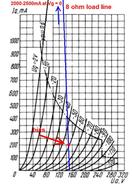
Your own load line tells the story... I guess you can call it class aB, perhaps with a very small "a", for all practical purposes, most OTL output stages including this one, operate in class B1. Also, with a few exceptions, class B is not biased at "exactly 0mA", it is low, but not that low.
I dont think you can classify something with "low, but not that low". What is the exact bias current value where you differentiate between class AB and B? We are talking about clear cut differences here. My amp has a part where both devices are conducting around the crossover region, hence it is class AB. If both devices never conduct at the same time, it is either class B or class C.
200mA is not even that low. Linn-topology transistor amps like AKSA and Rod Elliott's P3A project are biased around 100mA and it still makes them class AB.
200mA is not even that low. Linn-topology transistor amps like AKSA and Rod Elliott's P3A project are biased around 100mA and it still makes them class AB.
Let's not beat on that dead horse again with class AB vs. B. I am not saying it is not class AB, just that it has small class A relative to B, thus the small "a".
Okay.. sorry, never realized there was ever a debate on this on the audio realm. I thought it was a clear cut case.
- Status
- Not open for further replies.
- Home
- Amplifiers
- Tubes / Valves
- Another Approach to Totem Pole OTL Amplifier