")
I hope so Hugh, it is my first touch to bimo's amplifiersA very nice design....... I will be very interested, Thimios, your thoughts on the sound quality. It has VERY low THD, of course.
HD
I hope so Hugh, it is my first touch to bimo's amplifiers
Is this one with OITPC?
Is this one with OITPC?
Yes, according to bimo answer.
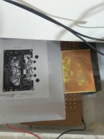
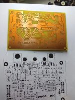
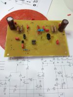
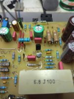
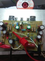
Is tis your first job done with PCB ?
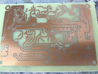
I did a lot of work with PCB yours is great ... but try to reduce the diameter of the holes in the copper foil .... as small as you can only to give a center to start the drill bit, then you will keep as much copper as possible ... soldering will be easier and stronger.
I did a lot of work with PCB yours is great ... but try to reduce the diameter of the holes in the copper foil .... as small as you can only to give a center to start the drill bit, then you will keep as much copper as possible ... soldering will be easier and stronger.
JMF,
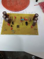
The TO92s are rated to 625mW and should do reasonably as drivers IFF the rail voltage is no more than 42V. I agree, they are pushed, but I have found they last OK at low power and particularly if the outputs have high beta.
Can answer for Bimo but the BD139 makes a great temp sensor because it can be bolted to a TO3P, a convenient thermal connection and quicker than on the heatsink.
HD
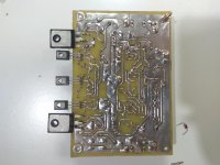
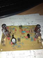
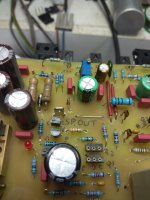
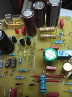
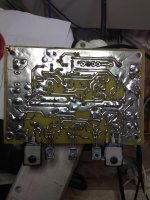
More photos.
Where is bimo?
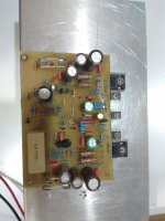
Is it a tested pcb or i must check for errors?
I see 0.5v across R22.
Where is bimo?
Is it a tested pcb or i must check for errors?
I see 0.5v across R22.
Attachments
Last edited:

- Home
- Amplifiers
- Solid State
- Anistardi Peletuk