No problem Carlo
Traction on either pulley should work I think. Tensioning mechanism is not necessary, that job can be done by tolerance on the rubber or other covering.
Traction on either pulley should work I think. Tensioning mechanism is not necessary, that job can be done by tolerance on the rubber or other covering.
elastic substances have the defect of deforming over time (the problem of old Lenco TT even with far bigger tolerances needed): so better to provide a resting position without contact between the pulleys. the belt would not have this problem.
I can not manage the resolution of forces (I solve the individual parts but not the whole system) but in two or three weeks I should be able to make a very simplified test arm
carlo
pulley sector: working on this
I can not manage the resolution of forces (I solve the individual parts but not the whole system) but in two or three weeks I should be able to make a very simplified test arm
carlo
pulley sector: working on this
Attachments
Last edited:
Hi Hiten
I'd prefer no band at all, all that's needed is fixed main pivot pulley, CW moving crank carrying CCW moving pivot pulley.
I am afraid the pulley carried by the crank is moving CW, the drawing in #1642 of Carlo is faulty. Am I missing something?
sorry about that carlo.Hiten - Rolamite: no, please, I beg you... you're putting too much stuff in the soup
Rolamite is for linear displacement, and nobody uses since his brilliant invention
carlo
Regards
You are right, I've made such a basic mistake. I'll have a look at it again.I am afraid the pulley carried by the crank is moving CW, the drawing in #1642 of Carlo is faulty. Am I missing something?
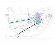
you'r right alighiszem: i've copied the pulley in that position without making the second turn. My intention was to show a possible shape for pullleys,
Sorry for that.
c
Sorry for that.
c
I think the belt idea looks promising. Rather than one continuous belt I would suggest two separate strings. One end of each securely attached one of the pulleys. The other end would be attached to the other pulley via a tensioner. This would eliminate the possibility of belt slip. Also the strings can be made of a highly flexible non stretch material so alignment remains consistent. The tension can be adjusted to give lowest possible bearing friction. Again I would highly recommend using jewelled pin bearings rather than ball race bearings as the level of friction is much lower. By slackening one string and tightening the other the relative positions of the two pulleys can be easily adjusted. Just a thought.
Niffy
Niffy
Niffy, maybe it's easier to glue the belt in a single point with a little bit of Loctite, as I said before.
I would like to ask everyone a favor*: the Syrinx seemed to be promising and not only to me, but looking at fleas (skating and so on) I did not notice an error as big as an elephant.
Since this seems less promising, it's there a chance that could work: but let's wait to test the prototype, or an expert that could do the calculations and tell us not to waste time with this idiocy.
This weekend I'll start to make some parts.
Carlo
*Do not believe in bad luck, but I'm Italian guys....
Hi Carlo,
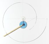
It might be worth your while to build a measurement rig to enable you to accurately determine the side force required to move the arm. This is what I did when developing the bearings for my arm. As my arm is a linear tracker the rig will be different than you would require but the same basic principle can be used. Unfortunately my camera was playing up when I took this picture but it should give you the general idea.

Like your previous rig it uses a pendulum. The pendulum is hung from a slider that runs on a couple of linear bearings that are pretensioned with a couple of springs to prevent slop. The slider is moved by turning the handle seen in the top right of the picture. The handle is attached to an M3 threaded rod so that one revolution moves the slider by 0.5mm. The thread of the pendulum is made from a couple of strands from a piece of dental floss and has a 6g weight at its end.
For my tests I used a mock up carriage that had the same mass and bearing spacing as my actual carriage. The string of the pendulum contacted a rod protruding from the mock up carriage at exactly the same location as the stylus would be. The drop was about 150mm.
One full rotation of the handle equates to about 0.2mN of side force. Start with the string just touching the rod then slowly wind the handle until the carriage moves. A bit of trigonometry and you can calculate the exact side force and the coefficient of friction of each bearing. I repeated this process about three hundred times for each bearing type. Time consuming. From this I could plot a graph of c.o.f. against probability. This told me not only average friction but also the mode (the most common friction) and the consistency of the bearing. Ideally you want low friction that doesn't vary much.
The graph below shows some of the bearings tested. A taller peek further to the left shows a more consistent lower friction bearing.

These are of course for a linear arm so are not applicable to your arm but gives an idea of my development process. I hope that this is of use to you.
Niffy
It might be worth your while to build a measurement rig to enable you to accurately determine the side force required to move the arm. This is what I did when developing the bearings for my arm. As my arm is a linear tracker the rig will be different than you would require but the same basic principle can be used. Unfortunately my camera was playing up when I took this picture but it should give you the general idea.
Like your previous rig it uses a pendulum. The pendulum is hung from a slider that runs on a couple of linear bearings that are pretensioned with a couple of springs to prevent slop. The slider is moved by turning the handle seen in the top right of the picture. The handle is attached to an M3 threaded rod so that one revolution moves the slider by 0.5mm. The thread of the pendulum is made from a couple of strands from a piece of dental floss and has a 6g weight at its end.
For my tests I used a mock up carriage that had the same mass and bearing spacing as my actual carriage. The string of the pendulum contacted a rod protruding from the mock up carriage at exactly the same location as the stylus would be. The drop was about 150mm.
One full rotation of the handle equates to about 0.2mN of side force. Start with the string just touching the rod then slowly wind the handle until the carriage moves. A bit of trigonometry and you can calculate the exact side force and the coefficient of friction of each bearing. I repeated this process about three hundred times for each bearing type. Time consuming. From this I could plot a graph of c.o.f. against probability. This told me not only average friction but also the mode (the most common friction) and the consistency of the bearing. Ideally you want low friction that doesn't vary much.
The graph below shows some of the bearings tested. A taller peek further to the left shows a more consistent lower friction bearing.
These are of course for a linear arm so are not applicable to your arm but gives an idea of my development process. I hope that this is of use to you.
Niffy
Thanks Niffy, very interesting and sophisticated rig, maybe could be modified for radials, and one day I will try it.
To speak now of bearings, however, is to put - il carro davanti ai buoi - the cart forward to the oxen we say here, because first we need to understand if this belt Birch can work.
As Alighiszem, I feel that something is wrong, but my physics studies are so old that I'm not able to convert the force for rolling the pulley on the belt in what causes the crank rotation. The 2wice solution seems simpler but even there the problem may be the same, as he noted clearly.
I hope that someone could tell us if and how this system can work, or avoid me another useless effort
carlo
Hi Carlo, 2wice,
I think the problem with the roller idea is that of rolling resistance. To minimize rolling resistance all of the rolling elements need to be very hard. This will tend to result in a low coefficient of friction between the separate components which would lead to slippage, not necessarily during play back but highly likely during queuing. Using rubber wheels to eliminate this slippage will result in a high rolling resistance and therefore high friction. A possible solution would be fine tooth gears but I'm sure that this would introduce more problems than it solves.
Hence my preference for the belt/string idea.
Niffy
Hi Carlo, 2wice,
I think the problem with the roller idea is that of rolling resistance. To minimize rolling resistance all of the rolling elements need to be very hard.
Niffy
Hi Niffy
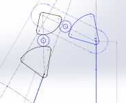
What about something like this?
2 Cams, one fixed, idler and the other cam on Sapphire rod and cylinder bearings. The idler is 10mm Sapphire cylinder.
Hiten's idea for the Rolamite tickled my fancy because of cost, very low friction and ease, start and end belt positions below.
Attachments
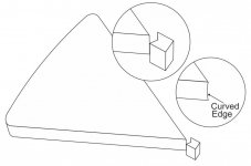
The Guitar Puck shaped Pulley can have vertical knife edge bearing to lower the friction. See pic attached. The Ribbon/Belt will hold the pulley against the knife edge bearing. The Knife edge will be little curved (Shown little exaggerated) to further reduce the friction.
Regards
Regards
Attachments
Very nice Hiten.
That would be much better than another rolling or sliding element and that leaves only the crank and cam as such.
That should be manageable.
If the crank is counterweighted a dual pivot and jewel cup bearing could be used.
Somewhat complicated though.
I like that warps might be less of an issues here.
Hi 2wice, what is the reason of the idler wheel? I can not understand, it turns the right way with just two (attachment)
Hi Niffy: between those two wheels or cames there is no relative motion, so (almost) no friction, as for the belt. Instead there is the risk of slippage and non-uniform contact (eccentricity, deformations of the materials & so on) which is absolutely to avoid. The gears could be perfect, with perfect LPs, perfectly centered (no reverse backlash)
c
No one playing with vectors? I'll have to switch on my lathe..
Attachments
Hi Carlo
It reverses the rotation of the moving cam.
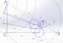
The angle needs to increase by 42.58°.
In your model when the 2 pulleys are only linked by string it works as you describe.
It reverses the rotation of the moving cam.
The angle needs to increase by 42.58°.
In your model when the 2 pulleys are only linked by string it works as you describe.
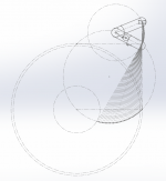
Tried to fit the cam + strap mechanism to my August 2017 drawings and it fits OK.
3 nulls, 0° to 0.4° to 0° to (-1.1°) - 0°
Can reduce the -1.1° at the expense of increasing the 0.4° error slightly and only 2 nulls then.
Should be able to get sub 1.° errors across the record by using some offsets and reducing the moving crank length somewhat.
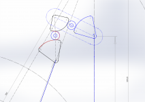
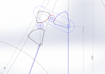
Bottom bar + cam is fixed, top crank cam & idler rotates in Rolamite config.
You can reduce the tracking error by increasing the moving crank length, but this looks manageable.
3 nulls, 0° to 0.4° to 0° to (-1.1°) - 0°
Can reduce the -1.1° at the expense of increasing the 0.4° error slightly and only 2 nulls then.
Should be able to get sub 1.° errors across the record by using some offsets and reducing the moving crank length somewhat.
Bottom bar + cam is fixed, top crank cam & idler rotates in Rolamite config.
You can reduce the tracking error by increasing the moving crank length, but this looks manageable.
Attachments

- Home
- Source & Line
- Analogue Source
- Angling for 90° - tangential pivot tonearms