schuch mk2 mockup
between saying and doing ....Nice on paper, a nightmare to build
Why? for 3 reasons
W - Wheel - can not follow such a tight curve
J - Joint - rotating + sliding means chattering.
G - Guide bar - acts like a variable counterweght
Damn, I was hoping a wheelbarrow would turn better than a rickshaw - for me that's enough
Carlo
good old vectors
In linear tangential tonearms the arm is tangent by definition (no twisting, hopefully), so only the cantilever may bend sideways to move it all, and not from the best position. (This is'nt written in their advertising: 0 offset, no tracking error, no distortion.....).
This only tryng to say that if we want to move an arm, we need some side force (yes, not too much = skating).
Is it better to leave this task to the cantilever's bending, or to use an offset pivot to get it? - Maybe normal tonearms geometry is less stupid than whe think.
Attachments
between saying and doing ....Nice on paper, a nightmare to build
Why? for 3 reasons
W - Wheel - can not follow such a tight curve
J - Joint - rotating + sliding means chattering.
G - Guide bar - acts like a variable counterweght
Damn, I was hoping a wheelbarrow would turn better than a rickshaw - for me that's enough
Love the mock ups! Your graphic and craft skills are an asset to this thread!
Using the spindle as a guide is not practical, especially when there's vertical movement involved, unless the arm moves only horizontally.
Looks like you're using the Thales circle and if so you can try something like this: the converging point of W can be a pivot bearing dealing only horizontal movement, and have a horizontal track, two rods for two ball bearings to roll on forming an axle also acting as vertical bearing that's attached to a main arm, from stylus to cantilever to pivot forming a straight line. As the whole assembly swings closer to the spindle, the main arm rolls forward accordingly, therefore you have an arm that is changing length as it tracks closer to the spindle. This forward movement needs to be articulated obviously and that's where the creativity comes in: building a guiding mechanism. The advantage is that I HOPE this passes diyrayk's string test as the stylus, cantilever, and pivot forms a straight line.... except the length of this straight line changes dynamically. The W movement is a curve so we have to make sure the arm moves smoothly. Perhaps a third wheel a la tricycle with the front wheel angle at 40° on the curved track would help. Or we can tie a string to the axle using the Birch geometry to guide the arm. Basically we want to make a passive (non-servo) arm that has no offset headshell, no pivoting headshell, no skating force, shared vector with groove, ONE horizontal pivot point, and moves forward as it gets closer to the spindle. How to accomplish that is up to your inventiveness.
Today, I'm just too lazy to rack my brain. 😀
Maybe normal tonearms geometry is less stupid than we think.
Not at all. That's why it's been around for 100 years! 😀
Sorry dear Directdriver,
is my bad english or my old brain? i'm a bit confused....
Better for me to stay focused on our "off topic" 3points arm, with my beloved Baerwald&Co geometry and K.I.S.S. technology.
I'll build one, after my JE Labs third rewiring. (wanna go under 4mV humm with AC heathers, sooner or later)
Carlo
is my bad english or my old brain? i'm a bit confused....
Better for me to stay focused on our "off topic" 3points arm, with my beloved Baerwald&Co geometry and K.I.S.S. technology.
I'll build one, after my JE Labs third rewiring. (wanna go under 4mV humm with AC heathers, sooner or later)
Carlo
Attachments
Sorry dear Directdriver,
is my bad english or my old brain? i'm a bit confused....
Lovely drawing again! It's my fault as I didn't explain it well enough. Just think of the Dynavector "split-plane" tonearm without the offset, a straight arm. But the front section slides on rails, therefore the arm's total length increases while tracking closer to the spindle. Hope that helps.

it was a joke, a xmas card. against the first - ridicolous - digi cameras. (3 Sinar put toghether)
But now your words make me think: she was always saying "change that, and this...
ciao carlo
But now your words make me think: she was always saying "change that, and this...
ciao carlo
Last edited:
dreamland
Basically we want to make a passive (non-servo) arm that has no offset headshell, no pivoting headshell, no skating force, shared vector with groove, ONE horizontal pivot point, and moves forward as it gets closer to the spindle.
How to accomplish that is up to your inventiveness....
crude reality
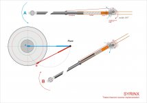
First efforts of my "inventiveness": change tack
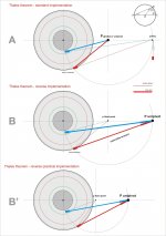
A - Take a standard Thales theorem tonearm (the simplest available, no fancy implementations).
B - Then put the main arm in place of the control line, and vice versa.
B' - Then reduce all to minimal size (330 mm ca main arm).
Now you have just to deal with an "extensible" arm. Start thinking, diyers
carlo
Basically we want to make a passive (non-servo) arm that has no offset headshell, no pivoting headshell, no skating force, shared vector with groove, ONE horizontal pivot point, and moves forward as it gets closer to the spindle.
How to accomplish that is up to your inventiveness....
crude reality
First efforts of my "inventiveness": change tack
A - Take a standard Thales theorem tonearm (the simplest available, no fancy implementations).
B - Then put the main arm in place of the control line, and vice versa.
B' - Then reduce all to minimal size (330 mm ca main arm).
Now you have just to deal with an "extensible" arm. Start thinking, diyers
carlo
Attachments
a little step
Beautiful the Thales geometry (someone says that the greek was a genius!), awful my control line (resonances, skating and ....aesthetics).
So I removed it: but how do you respect the theorem without a cathetus? It would be necessary that the arm will stretch automatically, following the right path.
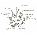
With two gears maybe it can be done, converting the rotation into an extension (see attachment)
Unfortuntely the extension is not linear, so the pulley (3) is not a circle but a cam, to be calculated.
carlo
Beautiful the Thales geometry (someone says that the greek was a genius!), awful my control line (resonances, skating and ....aesthetics).
So I removed it: but how do you respect the theorem without a cathetus? It would be necessary that the arm will stretch automatically, following the right path.
With two gears maybe it can be done, converting the rotation into an extension (see attachment)
Unfortuntely the extension is not linear, so the pulley (3) is not a circle but a cam, to be calculated.
carlo
Attachments
It would be necessary that the arm will stretch automatically, following the right path.
With two gears maybe it can be done, converting the rotation into an extension (see attachment)
Unfortuntely the extension is not linear, so the pulley (3) is not a circle but a cam, to be calculated.
Your implementation is too hard to materialize. A stretching arm will have varied effective mass. And the spring will only add unnecessary vibration. And the pistonic sliding of the inner tube against the outer tube also adds unnecessary friction.
It is best to have a "split-plane" design. Separating the horizontal movement from the vertical. Have a rotating horizontal bar that the vertical arm to ride on two wheels. The verical arm will just be a straight conventional tonearm with counterweight and no offset at the headshell. The two v-groove ball bearings will be riding on two round rods moving forward. It's just like a rickshaw rolling on straight tracks.
Guiding mechanism will be up to you and your creativity.
More or less your doubts are mine too, dear Directdriver.
But, as being said, even the bumblebees can fly, and linear tonearms sound good.
The system you describe: I went to re-read the posts on "tricycles" without being able to really understand what you say, and to which geometry are you referring now. Especially the "rotating horizontal bar that the vertical arm to ride on two wheels". May you post a little sketch? (no matter if nice or not).
Still some perplexity about the separation of planes (Triplanar & Co style), since I've has always tried, in my diying, to cross the axes in a single point, aligned to the stylus tip.
Now some explanations of that graphs
Effective mass - it's not that what worries me more (because I'm not able to calculate a mass so complex?): it is the elongation of one arm of the lever, that will increase the VTF. For a 12 "inch arm, the elongation is 10% ca, and so will increase the VTF (not so terrible). This happens tracking the internal grooves, where the tracking speed (and therefore the stylus drag) is smaller: will it be good or bad?
Stretching arm - the real problem. In the first graph (arm = cathetus, string= radius), like in other solutions with 2-3 pivots and sliding guides - movement is only due to the stylus drag, that is a variable force between 0.001 N and 0.0005N. (data found on the net) - Very little: a really frictionless stretching is needed, quite impossible to achieve without play. Linear ball bearings, square shaft scrolling directly on the pivot came in mind trying to find a solution.
This 2° idea (no radius string) instead is a system that gives an elongation geometrically tied to the rotation torque at the pivot point (far bigger force), not from the stylus drag. It is the system (spring+ gear) that drives the stretching, so piston tube friction + viscous fluid may help to get a smooth movement and dampen the resonances. And now the friction does'nt affect the tracking, since there is no direct relation. (hopefully)
Spring + gears - The spring should be long as the arm, thin and adjustable (the arm should not rotate by itself) - of course it will be dampened together with the tube. Gears: lot of work to design a clever solution (and to buy the right ones)
Ciao - Carlo
And what about the geometry? if it's good, solutions will come
sooner or later, and "with a little help of our friends"....
I go away for a few days and you guys add ten pages to the thread. Carlo's fertile imagination, drawings, and models make catching up a pleasure. I'm seriously envious of his abilities. Drawings are important, but mockups or models allow for both "Ah, nuts" and "Hey, that'll work" moments.
I've come to the conclusion the first Schuch is an abstract of what he's trying to accomplish is probably can't be built.
I tried diyrayk's string test (#949) on some of my linear pivot arms and they apparently failed, which disappointed and puzzled me, but what caused the "failure" was the control arm swinging toward the spindle and pushing the arm forward. In other words, doing exactly what it's supposed to from moment to moment. The actual pivot is back at Birch point B - or at a virtual point in the Schroeder case - and the stylus is always in line with that so, while there are side forces, there is no skating.
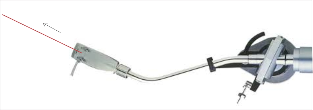
Finally, the photos may show a way to do Carlo's three point pivot (#1217) without physical bearings. DD, this emerged, partially, out of your question about adapting Simon Yorkes' design to Birch geometry.
I've come to the conclusion the first Schuch is an abstract of what he's trying to accomplish is probably can't be built.
I tried diyrayk's string test (#949) on some of my linear pivot arms and they apparently failed, which disappointed and puzzled me, but what caused the "failure" was the control arm swinging toward the spindle and pushing the arm forward. In other words, doing exactly what it's supposed to from moment to moment. The actual pivot is back at Birch point B - or at a virtual point in the Schroeder case - and the stylus is always in line with that so, while there are side forces, there is no skating.
Finally, the photos may show a way to do Carlo's three point pivot (#1217) without physical bearings. DD, this emerged, partially, out of your question about adapting Simon Yorkes' design to Birch geometry.
Attachments
Last edited:
I tried diyrayk's string test (#949) on some of my linear pivot arms and they apparently failed, which disappointed and puzzled me, but what caused the "failure" was the control arm swinging toward the spindle and pushing the arm forward. In other words, doing exactly what it's supposed to from moment to moment. The actual pivot is back at Birch point B - or at a virtual point in the Schroeder case - and the stylus is always in line with that so, while there are side forces, there is no skating.
Welcome back Doug. I think the Birch pivot point is at P so it's not in line with the stylus and cantilever, hence the failed string test. That's why I want to try a fixed point B as the pivot in this what Mark Kelly called "split-plane" design with a twist using pivot bearing AND linear bearing: a pivoting horizontal bar with rollers riding on it to make an "extending arm" as it tracks closer to the spindle. The guiding mechanism, as always, will be tricky.
Finally, the photos may show a way to do Carlo's three point pivot (#1217) without physical bearings. DD, this emerged, partially, out of your question about adapting Simon Yorkes' design to Birch geometry.
That's what I've been trying to tell him! Thanks, Doug. You're the model member of this thread (pun intended). The Pro-Ject Signature unipivot tonearm uses the same concept.
I don't think you even need two side bars, which would make three contact points, one is suffice because if you make the mass lean on one side it creates only two contact points, like the idea of the Basis Vector arm or the Durand Telos. I say one right side bar would work if you have a straight arm with offset headshell as the arm's mass will lean on the right side.
Oops, off topic again!
Have a Happy 4th of July, fellow Americans!
Last edited:
dear Dd.
some trials, trying to learn something about tricycles (were so funny, as a kid!) and guides.
May be useful?
3rd modification to my Thales: I found that the elongation is almost linear, with respect to the angular motion: so, look ma, no gears! - It's becoming diyable? I'll make some tests
Doug: thanks for the photos: is it a magnetically stabilized unipivot? clever!
As diyer I'm experimenting various types of articulation, trying to simplify to the maximum - even too much, sometimes - This 3points - neither gimbal nor unipivot - attracts me, but before switching on the lathe a better design has to be found.
ciao - carlo
Attachments

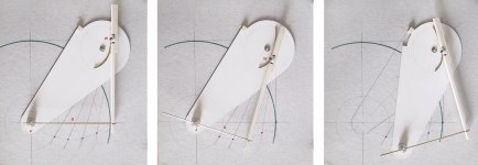
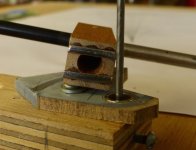
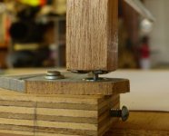
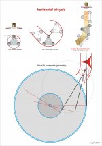
Second episode: mock up of the horizontal tricycle.
Runs smoothly on this cardboard guides, with wheels made with washers. No problem with tight curves, that was my goal. The second version, with inner guide, would be much easier to build, and nicer to see.
From this mock up to a real, working arm, it's a long way.
ciao carlo
Runs smoothly on this cardboard guides, with wheels made with washers. No problem with tight curves, that was my goal. The second version, with inner guide, would be much easier to build, and nicer to see.
From this mock up to a real, working arm, it's a long way.
ciao carlo
Attachments

tricycle geometry
Carlo, great drawings and modeling again! I need to let you know the tricycle geometry has been explored by member 2wice in post#1130 but Straight Tracker raised the issue of skating force in post#1132 and 1142 or you can read all the related posts between page 113 to 117. Just so you know.
Carlo, great drawings and modeling again! I need to let you know the tricycle geometry has been explored by member 2wice in post#1130 but Straight Tracker raised the issue of skating force in post#1132 and 1142 or you can read all the related posts between page 113 to 117. Just so you know.
There is no doubt that your geometry would result in perfect tracking. However, the force pulling the tonearm along, will have to be controlled by an opposing force. If that is not done, the tonearm will overshoot and the cantilever will be deflected. I have been trying to design a tonearm moved by record fiction for years (since 2010) and I know what you're up against. The drag of the LP acts on the tonearm through a mechanical advantage which increases as the tonearm approaches the label area. That in turn means that the above mentioned opposing force has to increase as the tonearm nears the label area. On top of that, it is not a linear function. It is my opinion, that this problem cannot be solved without some kind of servo, be it mechanical, electronic or magnetic.
Your proposed geometry with either two or three curves has a virtual pivot somewhere to the left of the the tonearm's center line. That virtual pivot is not located in a fixed position, but wanders about as the radii of the curves become smaller. The fact that the direction of the drag force passes the virtual pivot on its right side, causes the tonearm to skate! The fact, that the drag force is governed by, a) the vinyl composition, b) the tracking force and c) the frequency content of the LP, makes it unpredictable and it will have to be controlled by some type of servo. I know this because my 2010 tonearm, functioning basically like yours, skated and it took me until two days ago to perfect it. A kind gentleman on the internet designed the electronic servo for me and now it works! It is a passive servo that provides just enough of an opposing force to the skating force to allow it to track with 100% accuracy. I am not trying to discourage you, but just to warn you, as to what to expect.
Thanks, I know all those posts - all copied into a file to study (and understand?) them carefully.
Two words about what I did: you told me to search solutions for the guides, and that I tried to do: seeing that a normal carriage fails to follow narrow curves, i've switched from trains (vertical wheels) to a rollercoaster (wheels horizontal or inclined), and it seems to work.
How to draw the guides:
1 - Trace on paper the required curve for the established arm length (better if enlarged)
2 - Set the pivot point on the tricycle (the one shown on the drawing - the geometric center is not good)
3 - follow the curve on paper with that pivot point, and let the 2 + 1 wheels draw the two curves (guides) for you -
The "inner guide" is much simpler to be fit to measure - note that the curves are not parallel
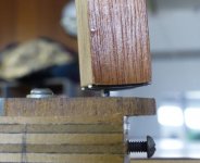
Results: pulling it (the fake arm is for that) with a string along the direction of tangency does not seem to bring problems - just a bit more resistance only for the narrower part of the curve (made much narrower than necessary, to test)
Still many perplexities on all the arms whose motion is controlled only by the stylus drag: (overshoot and so on, and more, where to place the cartridge to listen the third track?
But IMHO the pivot point, travelling along the guide is always aligned with stylus at tangency: no error or possible play with this tricycle (an issue with excentric LP !!)
ciao carlo
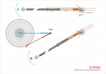
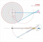
I'm making a model of the Syrinx: seems promising, and suggests new solutions
Two words about what I did: you told me to search solutions for the guides, and that I tried to do: seeing that a normal carriage fails to follow narrow curves, i've switched from trains (vertical wheels) to a rollercoaster (wheels horizontal or inclined), and it seems to work.
How to draw the guides:
1 - Trace on paper the required curve for the established arm length (better if enlarged)
2 - Set the pivot point on the tricycle (the one shown on the drawing - the geometric center is not good)
3 - follow the curve on paper with that pivot point, and let the 2 + 1 wheels draw the two curves (guides) for you -
The "inner guide" is much simpler to be fit to measure - note that the curves are not parallel
Results: pulling it (the fake arm is for that) with a string along the direction of tangency does not seem to bring problems - just a bit more resistance only for the narrower part of the curve (made much narrower than necessary, to test)
Still many perplexities on all the arms whose motion is controlled only by the stylus drag: (overshoot and so on, and more, where to place the cartridge to listen the third track?
But IMHO the pivot point, travelling along the guide is always aligned with stylus at tangency: no error or possible play with this tricycle (an issue with excentric LP !!)
ciao carlo
I'm making a model of the Syrinx: seems promising, and suggests new solutions
- Home
- Source & Line
- Analogue Source
- Angling for 90° - tangential pivot tonearms