From a DIY perspective, how can anybody not get a kick out of guitar string tuners repurposed despite concerns about string resonances?
Thank you for your perspective, Doug. You're the model member of this thread. Not only you get the spirit of this thread, you actually built an arm related to the theme!
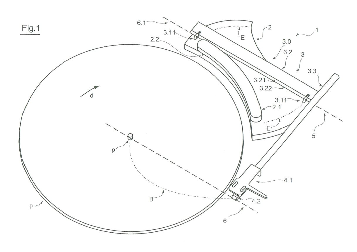
The double bearing arm in Fig. 1 is clever, but will probably have binding issues between the bearings sides and the groove sides. That can be mitigated with very precise wheels and grooves, but that puts the construction well outside most DIY.
I really like the simplicity of the Fig. 1 arm. I would place the counterweight at the opposite end of the main arm, sort of like the ET airbearing arm arrangement, for better mass distribution, like below. The wheels in grooves binding issue can be lessened with V-groove bearings on curved rods. The two wheels will be acting like dual unicycles going opposite directions. The whole tonearm can be made from a single rod with multiple bent angles from the headshell to the tail end of counterweight, with two ball bearings wrap around it.

I'd liked to have been around when Daniel Schuch realized he might be able to achieve the same design with strings.
No kidding! Isn't it amazing how the human thought process can arrive at certain ideas?!
I thought the Guha arm rotated control point B in the Birch geometry 90 degrees and a quick drawing I did yesterday seemed to confirm that, but today, after doing another drawing, it's clearer that the control arm slip/slides across the circular surface. One advantage the Guha arm would have over the Birch is that the plinth could be smaller although it shares the disadvantage of the headshell being parked quite close to the platter edge.
Thanks for drawing my attention to the Guha geometry. The drawings were confusing so I was just too lazy to figure that out. Then I realized part#48 is stationary and everything starts to make sense. It looks like just another Birch variant but as you confirmed that point B is not a fixed point so it's closer to Schroeder LT geometry. The Guha doesn't seem to have any antiskating mechanism built in and it might, as some suspect, skate like crazy.
Dream
Two only bearings for an error-free geometry are really a dream.
But maybe I'm too old to understand such a clever design (fig 1), or to believe in dreams.
Please try to explain me how it works, since imho if there are two wheels traveling through a circle the arm moves just around the O pivot, which is ok only in A1 and A2 position (attachment)
But in the case of the Schuch arm, the arm's pivot must move along the surface of the "hipflask" (B, C, positions). So or the wheels will slide out of the groove, or alter the distance from each other, or pivot on their axes (two more bearings).
That's why for me Herr Schuch went fastly to drawings 2, 3 and so on, with those guitar strings.
nightmare
.... maybe rotating the whole thing on the vertical plane, thanks to gravity the arm will swing gracefully on the flask - no bearings, no rails, or strings to be tuned
Attachments
Dream
since imho if there are two wheels traveling through a circle the arm moves just around the O pivot, which is ok only in A1 and A2 position (attachment)
No, the fulcrum is not static in point O, but moves along the curved guide. The wheels do not move on a circle.
Thanks Alighiszem, but still I do not understand that geometry: may you post a graph?
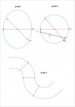
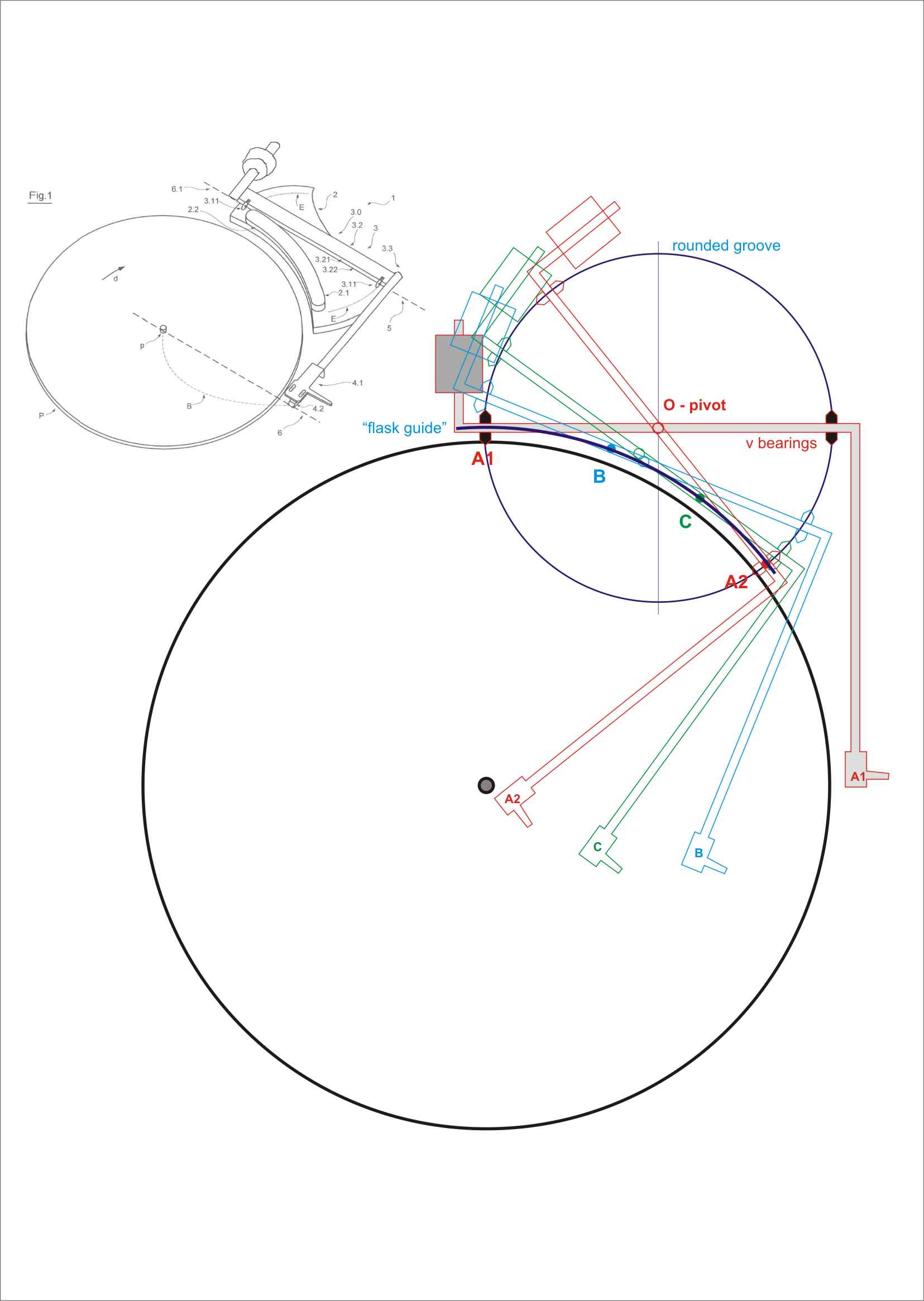
It seems to me that two fixed-distance wheels can only travel on a circle, or two parallel rails (like a train). (Graph 1 - 2 - 3).
If (as you rightly noted, and as I did in the previous post) the fulcrum has to move from the center O to B, C or others on the guide, the distance between the wheels is no longer a diameter but a - corda - (in italian - rope? don't know the right term), so both the distance and the inclination of the wheels must be changed (Graph 2)
ciao Carlo
Attachments
If O-pivot is static, like the Birch geometry, then you need an extra pivot between main arm (the arm that holds the cartridge) and guide arm (the rod that holds the two wheels) to track tangentially. There is no static 'O' point in the Schuch arm. Don't forget the guide arm is ALWAYS touching the hipflask as part of the guiding mechanism when the arm moves across the record. You only really need one curved groove for the back wheel. The front wheel can be rolling on flat surface, without a predetermined groove, lead by the cartridge and guided by the back wheel and hipflask. Of course, it will still draw the same curved trajectory. Ultimately I believe the design and geometry starts with predetermined dotted Line B and works itself backward tangentially. I suggested a tricycle design before and you can think of the hipflask touching points as that third wheel.
The unique thing about the Schuch arm is that it has no pivot point horizontally. The intellectual perversity of the design is that it's literally taking parallel arm for a spin! I get a kick out of it. One can argue why not just build a parallel tracker on rollers a la Opus Cantus to save all the geometric headaches. The Schuch has the advantage of shared vector with the groove and less horizontal mass. Not sure how well it will work in practice and dealing with skating force but it is an idea out there.
The unique thing about the Schuch arm is that it has no pivot point horizontally. The intellectual perversity of the design is that it's literally taking parallel arm for a spin! I get a kick out of it. One can argue why not just build a parallel tracker on rollers a la Opus Cantus to save all the geometric headaches. The Schuch has the advantage of shared vector with the groove and less horizontal mass. Not sure how well it will work in practice and dealing with skating force but it is an idea out there.
Many thanks dear DirectDriver, fogs are beginning to disappear.
That the Schuch arm does not have one fixed pivot, but rolls on the "flask" surface was perfectly clear (if not it would be just a "normal" arm, drawn by a crazy).
I simply pointed out that if it rotates on two wheels as in fig 1, this was exactly what would happen: a virtual fixed pivot.with the arm moving far from the flask, except in A1 and A2.
I had been driven out from those two dotted lines near the wheels in fig 1 and the Gtut post:
"The double bearing arm in Fig. 1 is clever, but will probably have binding issues between the bearing sides and the groove sides." It can be mitigated with very precise wheels and grooves, but that puts the construction well outside most DIY. "
So, if I understand your description, this no-string version rotates on back wheel along a rail, rolls on the hipflask surface while the front wheel slides freely. This makes sense even if, trying to redraw it, also the back wheel seems not to follow the rail correctly.
Thanks to your thread i know Birch geometry and others based on 3 or more pivots, tricycle design included. I still consider the string-guided Thales tonearm one of the smarter solutions, even if a bearing directly above the stylus is not at top of my short list. This Schuch arm is really intriguing, if one could find a clever diy way to build it: possibly without strings, wheels, sliders and so on: maybe just a strip of mylar over the flask?....
Carlo
So, if I understand your description, this no-string version rotates on back wheel along a rail, rolls on the hipflask surface while the front wheel slides freely. This makes sense even if, trying to redraw it, also the back wheel seems not to follow the rail correctly.
Any wheel on a curved track will have binding issue as Doug predicts. I think V-groove ball bearing on curved round rods can probably lessen that, which has 2 contact points per wheel. It's still tricky as the two wheels are also acting as the bearings for the arm's vertical movement so they cannot be angled.
I'm not sure how the arm reacts on eccentric records either... Will the arm lose contact with the hipflask? I might be wrong suggesting not using a track for the front wheel because eccentric records can fling the arm backward and there's nothing to force the arm keeping in contact on the hipflask. Maybe the use of magnet can help? I don't know... The dynamic behavior of such arm is unpredictable and this may have led the designer to the string design. Unless someone can create a prototype to test it, this design will have a lot of question marks. Such a shame, as it possesses potential.
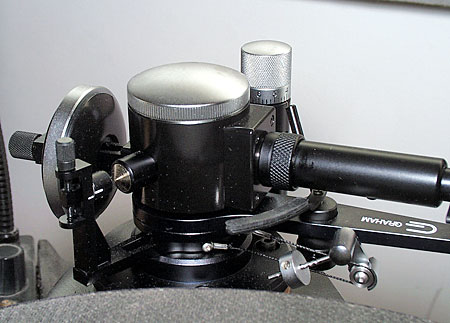
I still consider the string-guided Thales tonearm one of the smarter solutions, even if a bearing directly above the stylus is not at top of my short list. This Schuch arm is really intriguing, if one could find a clever diy way to build it: possibly without strings, wheels, sliders and so on: maybe just a strip of mylar over the flask?....
Yes, the Thales or Garrard Zero 100 is still the most DIYable of this genre, as long as you're not averse to having a bearing above the stylus. And the Schuch arm deserves a diy experiment too.
Completely agree, your knowledge is so vast ....
Unfortunately wheels (even the best possible, as Doug & you have suggested) do not work: can not be angled, and if they do their job properly on the rail, there would be a virtual fixed pivot and that would not be a Schuch arm anymore.
diying:
Schuch: a real challenge. The issues you have rightly pointed out are so many, and of difficult solution; That arm should roll on the flask guide without any play, and with the least inertia, which is far from the present situation.
Thales - that of # 40, not the Garrard-style (too many bearings for my taste). Have you seen my # 1178 post? I would like your sincere opinion before throwing away time in silly experiments
ciao Carlo
Have you seen my #1178 post? I would like your sincere opinion before throwing away time in silly experiments.
(post#1178: 30th April 2017, 03:21 AM)
just for fun
Silly idea. Never tried.
But when I'll get one cartridge (and some LP) to throw away...
I don't know what exactly is the mechanism to keep the tracking stylus tangent. How do you keep the so called "alignment stylus" in the same groove as the tracking stylus? Obviously the front stylus will have more skating force than the rear stylus, provided it's overhung. Both styli are a passive system guided by the groove(s) and nothing else. But I believe it needs another fixed point to force the tracking stylus to angle for tangency. Do you intend to add more parts to the design?
I don't think I understand the design, to be honest.
There are many ways to make pivoting headshells, too.
Besides the Thales clone as a DIY project or this one, you can also try one of Doug's designs, the quasi-Schroeder LT model, and I'm sure he can give you more tips and advice.
First of all thanks for your attention, Direct driver, and your always valuable remarks
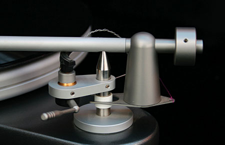
The starting (silly) idea came from the famous RS LABS rotary headshell. However, if the alignment of the bearing's axis with the stylus tip seems correct for the rotation, but not the best for self alignment, (well shown in this Italian thread that you know -http://ansaht.altervista.org/phpBB2/viewtopic.php?p=629&sid=f532909c59033aec534dda7e4e977ce9
For this second goal would be preferable a bearing aligned with the cantilever pivot, acting like a plow, or a pivoting wheel.
So I thought that a second stylus could be the pivot to align that of the signal with no offset. Both placed on a rotary head shell.
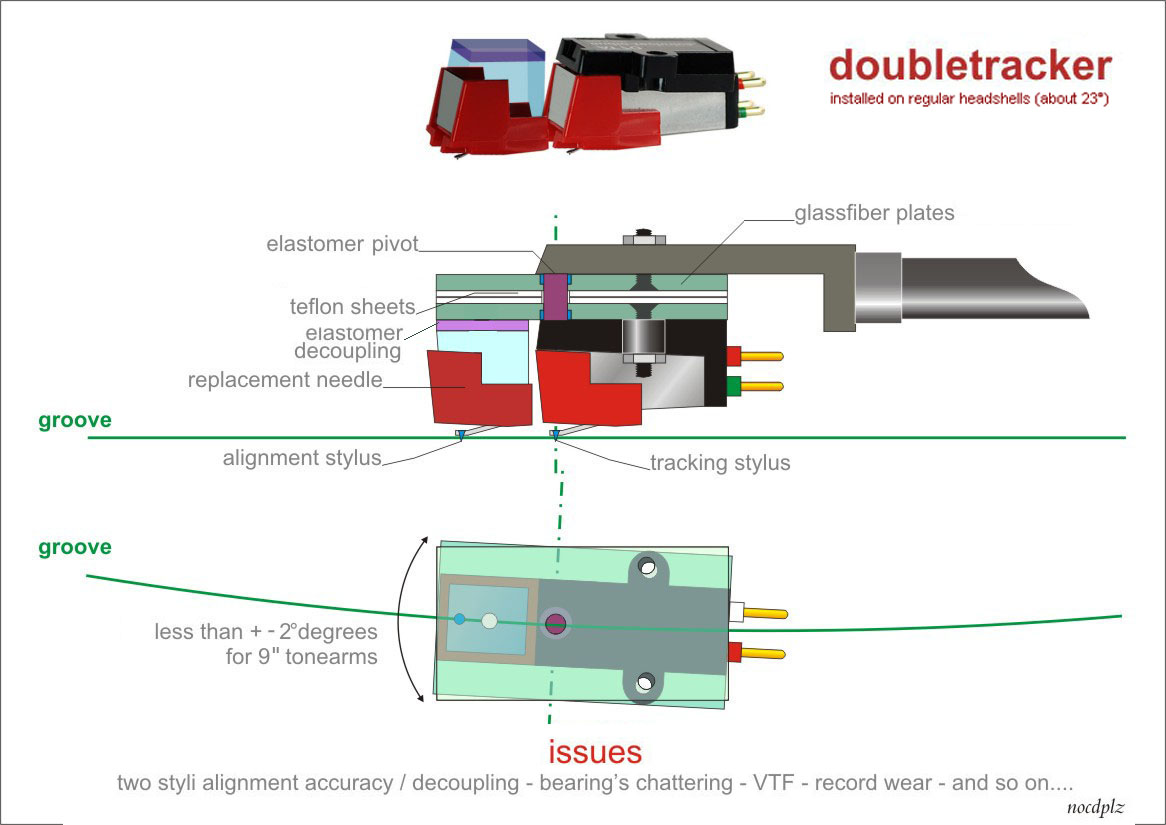
As you may recall from a previous chat, I've experienced enough bearing chattering not to look for simpler solutions, and since in this case the rotation is less than + - 2 ° I thought that a rubber or silicone elastic joint (like that of the cantilever) can suffice.
So the rotary shell is simply made with two sliding (teflon) plates with a silicon joint aligned with the tip of the signal stylus. (my graph is clear only to me!)
The problems (for the alignment the groove at the beginning of the LP may do the job, but even placed in the adiacent groove it's not a tragedy) are many, perhaps too many: VTF, two styli compliance, resonance de-coupling, LP wear and so on.
But I'm curious about it - si parva licet - even the Columbus egg was a solution to a useless problem.
carlo
The starting (silly) idea came from the famous RS LABS rotary headshell. However, if the alignment of the bearing's axis with the stylus tip seems correct for the rotation, but not the best for self alignment, (well shown in this Italian thread that you know -http://ansaht.altervista.org/phpBB2/viewtopic.php?p=629&sid=f532909c59033aec534dda7e4e977ce9
For this second goal would be preferable a bearing aligned with the cantilever pivot, acting like a plow, or a pivoting wheel.
So I thought that a second stylus could be the pivot to align that of the signal with no offset. Both placed on a rotary head shell.
As you may recall from a previous chat, I've experienced enough bearing chattering not to look for simpler solutions, and since in this case the rotation is less than + - 2 ° I thought that a rubber or silicone elastic joint (like that of the cantilever) can suffice.
So the rotary shell is simply made with two sliding (teflon) plates with a silicon joint aligned with the tip of the signal stylus. (my graph is clear only to me!)
The problems (for the alignment the groove at the beginning of the LP may do the job, but even placed in the adiacent groove it's not a tragedy) are many, perhaps too many: VTF, two styli compliance, resonance de-coupling, LP wear and so on.
But I'm curious about it - si parva licet - even the Columbus egg was a solution to a useless problem.
carlo
Last edited:
I don't know what exactly is the mechanism to keep the tracking stylus tangent. How do you keep the so called "alignment stylus" in the same groove as the tracking stylus? Obviously the front stylus will have more skating force than the rear stylus, provided it's overhung. Both styli are a passive system guided by the groove(s) and nothing else. But I believe it needs another fixed point to force the tracking stylus to angle for tangency. Do you intend to add more parts to the design?
I don't think I understand the design, to be honest.
There are many ways to make pivoting headshells, too.
Besides the Thales clone as a DIY project or this one, you can also try one of Doug's designs, the quasi-Schroeder LT model, and I'm sure he can give you more tips and advice.
I have seen that done with a brush instead.... no sonic benefits however 🙂
The Stanton-Pickering cartridge brush did not have this role (VTF stabilizer), it was not planned to mount them on a rotary headshell.
Probably mine is only a stupid idea, if I'll never build one and it works we'll talk about
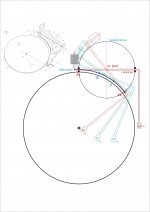
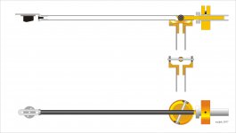
Now just a bit of "reverse engineering" trying to better understand the geometry of a Schuch arm. Graph drawn starting from the condition of tangency (no offset)
Tonearm (X and Y points) movements seem rather complex.
The path of the stylus (points A*B*C*D*) and the shape of the "hipflask" guide (points A B C D) look like simple circle arches.
hope this helps - carlo
Probably mine is only a stupid idea, if I'll never build one and it works we'll talk about
Now just a bit of "reverse engineering" trying to better understand the geometry of a Schuch arm. Graph drawn starting from the condition of tangency (no offset)
Tonearm (X and Y points) movements seem rather complex.
The path of the stylus (points A*B*C*D*) and the shape of the "hipflask" guide (points A B C D) look like simple circle arches.
hope this helps - carlo
Attachments
The tracking stylus and headshell would resonate at the rate of music content (a bit before the real stylus), and would eventually transfer this resonance to the real headshell. Quite like magnetic print-through at reel-to-reel tapes.
Just one of my fears, dear Icsaszar, and not the biggest one (see at the bottom of the graph) - maybe sorbothane de-coupling?
When someone starts to fight against offset issues (my suspect is that production tolerances in cantilever alignment are far bigger) must be prepared for everything, even to build a damn air bearing tangential.
But this is our toy, or not?
thanks carlo
When someone starts to fight against offset issues (my suspect is that production tolerances in cantilever alignment are far bigger) must be prepared for everything, even to build a damn air bearing tangential.
But this is our toy, or not?
thanks carlo
The Stanton-Pickering cartridge brush did not have this role (VTF stabilizer), it was not planned to mount them on a rotary headshell.
I did mount the stanton on a diy rotary headshell.
No good results at the time 🙂
No surprise dear RC: difficult task for a brush, and also for a second stylus, I fear.
But imho "sonic improvements" heard in diyng are often related to self esteem. (to $$$ when shopping)
And without the brush?
Carlo
But imho "sonic improvements" heard in diyng are often related to self esteem. (to $$$ when shopping)
And without the brush?
Carlo
Off topic, sorry
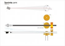
The "clever two-wheel design" is so fascinating that makes me think: with the problems seen in a Schuch geometry, why not use it for a "normal" arm?
A simple arm supported on three points (not unipivot, nor gimbal): his stylus tip and two wheels (or better, two steel or ceramic balls) on a round rail (attachment)
Seems so easy that surely it has already been tried before.
Any advice? Carlo
Attachments
A simple arm supported on three points (not unipivot, nor gimbal): his stylus tip and two wheels (or better, two steel or ceramic balls) on a round rail (attachment) Seems so easy that surely it has already been tried before. Any advice?
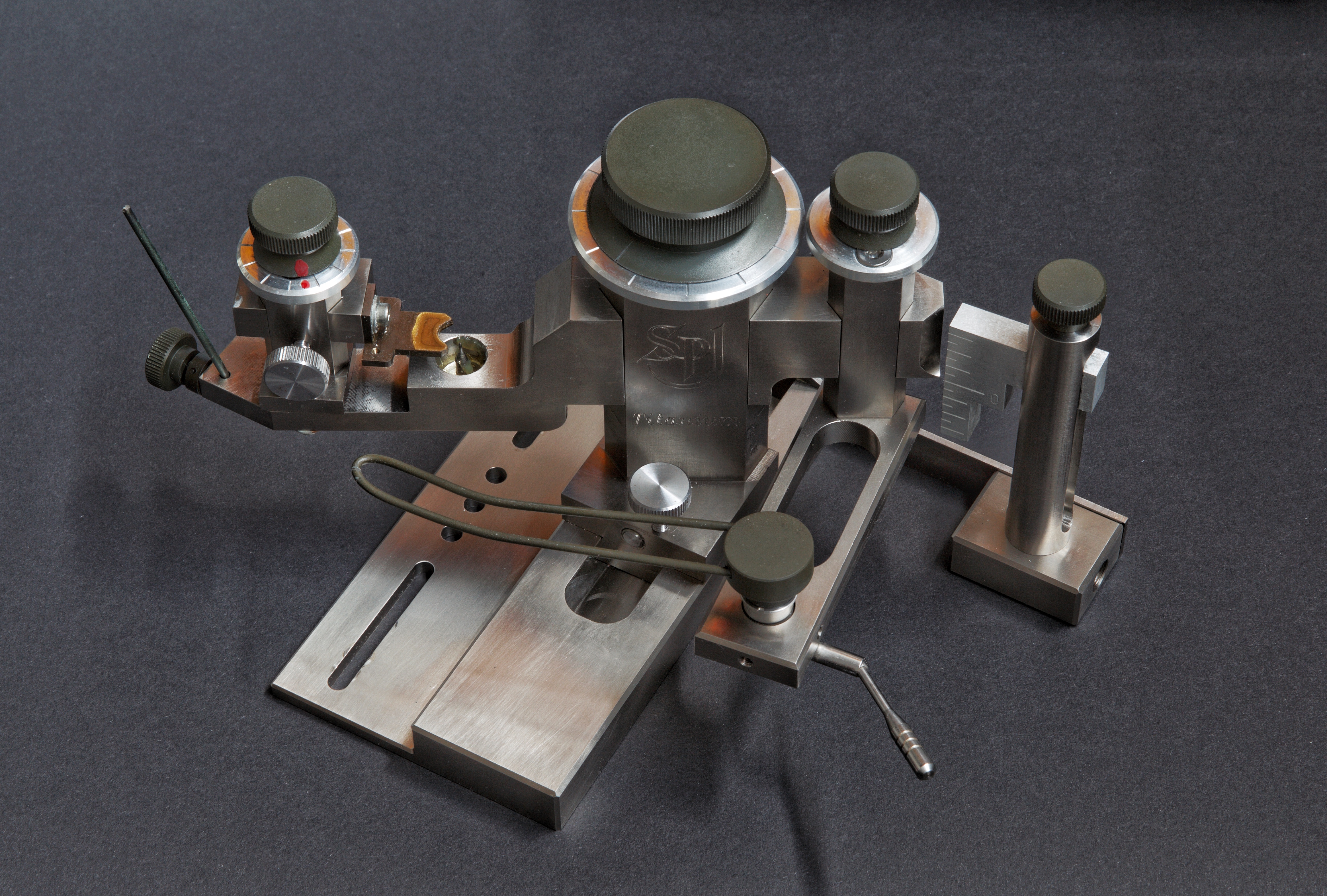
I like the idea of a three point support. But how do you keep the balls rolling smoothly without the top race sticking them. I'm sure there's a term for this type of motion, stiction? I think to keep the three point concept working, you're better off with unipivot design with a secondary bearing or support to avoid azimuth rocking. This way majority of the mass is concentrated on the main spike (one point) and forms a straight line with the stylus (one point) and a secondary rolling mechanism to form the third contact (one point). The Durand Telos is one example. Another example is to have ball bearing wrap around the main spike like the Basis Vector tonearm and Continuum Cobra and Copperhead or their pioneer of such design like the SPJ tonearm. Or simpler one like the Pro-Ject unipivot and Simon Yorke arm. or a less rigid design like the Graham Phantom using a magnetic guide.
If you can keep the balls rolling with no friction then you have a winner. You can still keep the two ball concept by having one ball as the center pivot and the side ball moves just like how you drew it. Now the main mass is on the center ball and the side ball has much less mass to deal with, hence less friction.
An externally hosted image should be here but it was not working when we last tested it.
I know this is off topic but aside from tangential tracking tonearms, one of my fascinations has always been unipivot designs with secondary bearing. 😀
maybe something like thisI would like your sincere opinion before throwing away time in silly experiments.
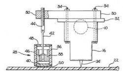
US patent 4151998
Phonograph tone arm and cartridge damping system
A phonograph tone arm and cartridge damping system in which a damper is coupled to a tone arm having a cartridge at one end thereof or to the cartridge itself and is adapted to ride on the surface of a record to minimize the effect of surface warps on the tone arm and cartridge.
The damper includes a housing, a low friction piston slidable within the housing, and a glider adapted to ride on the surface of the record. The piston has an orifice therethrough to permit ambient air forced through the orifice to serve as the damping medium, or the piston and the housing have a preselected spacing between them to allow ambient air to flow therethrough. The glider has attached thereto a piece of soft velure or pile fabric, or a plurality of brush tips, which act to minimize friction between the glider surface and the record.

Attachments
Dear Directdriver, your knowledge of tonearms always makes me wonder, everytime there is something new to learn, thanks.
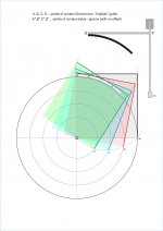
The problem that you have noted surely exists (started with two simple wheels - attachment - but as you know I do not like ball-bearings in tonearms, at least those I can get) but with no answers at present. Two ballpen tips "nanook-style" ? two teflon tips on a well lubricated rail? Who kows, it must be build, consider that angular speed is very limited.
Enlarging the previous graph you may see that the two balls are inside a v shaped hole above, and under roll on a v shaped rail - a solution used for some platter spindles -
Perhaps the asymmetric solution is smarter but I really fear that this asymmetry (a smooth rotation + a "stiction" of the wheel) could induce (pivoting on the wheel's friction) a tilting of the vertical axis, or some irregular motion. For me a correct azimuth is as important as offset issues, or more.
As diyer I like to go out of the beaten path, cloning or "improving" industrial items is almost insane, for me
What I can imagine is that the building, even with a good lathe, would not be trivial at all
Dear TVL thanks for the link - my goal however is not to dampen the VTF as with a stanton brush or this special device, but to use a second stylus to align with 0 offset the cartridge, mounted on a rotary headshell (mine has a strange design and the drawing it's not clear). Indeed the dampening caused from the second stylus could lead to irregular VTF (eg, the compliance of this stylus must be equal, bigger or smaller than the other?).
(too warped records: throw them away, and store well the others (personal solution))
ciao - Carlo
Making some sunday homeworks: a rough wooden mockup of the Schuch tonearm - mmm???
Attachments
Last edited:
- Home
- Source & Line
- Analogue Source
- Angling for 90° - tangential pivot tonearms