You are right I was referring to the blue curve, but I always thought the Birch P was centre of circle where mine was ellipse?
You are right I was referring to the blue curve, but I always thought the Birch P was centre of circle where mine was ellipse?
Yes, Birch P point is the center of a circle. But that is determined by the curve segment. It could be a part of a ellipse but you can merge it with a circle since you are only using a segment of it. The center point of the new circle can be calculated by math or using a compass, pencil and paper. To do it by math you can follow Mark Kelly's instruction in post #219 and #222.
The original patent point "P" was referred to as "C". First you find the curve and THEN you merge it with a circle whatever the size it may be and then find the center point, which is "P" or "C".
An externally hosted image should be here but it was not working when we last tested it.
An externally hosted image should be here but it was not working when we last tested it.
2wice,
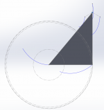
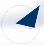
I just did a down and dirty drawing of what I think you have in mind and got an ellipse arc for the motion of the pivot. The circles of the Birch geometry are the result of the constraints imposed by the combination of "P" and "B" in the lower drawing in #1122. I believe the approach you are taking is closer to the Schroeder geometry since there is no fixed "B" and will be more accurate than the Birch geometry.
Regardless, you've put a lot of time and energy into designing a unique pivoting linear tracker and I hope you can pull it off.
Last edited:
Thanks Doug
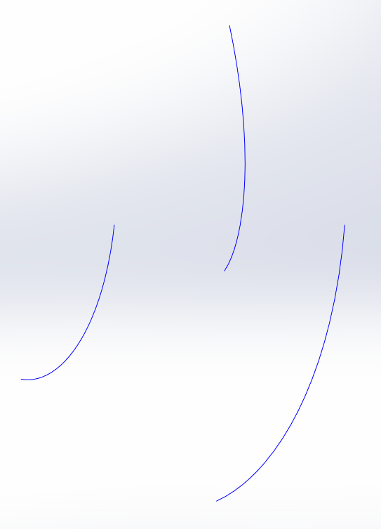
It is I think, very close to the Schroeder geometry, but the blue curve is the arc of his moving pivot.
I wanted to steer clear of his magnetic guide curve and tried to implement something using only the moving pivot curve, but it requered frictionless linear bearings 🙁 ie: impossible.
https://youtu.be/b2W813RKuQY?t=15
The simplest method is using the Schroeder magnetic guide curve and it is inspired. It is a simple matter to calculating the magnetic guide curve equation. For any arm length, they are all just scaled version of the same equation of an arc of an ellipse.
youtube stiction?
I see what looks like a severe case of stiction in the last second of the youtube video, and isn't that the point in the motion where the cartridge would be negotiating the inner grooves??
Ray K
I see what looks like a severe case of stiction in the last second of the youtube video, and isn't that the point in the motion where the cartridge would be negotiating the inner grooves??
Ray K
I see what looks like a severe case of stiction in the last second of the youtube video, and isn't that the point in the motion where the cartridge would be negotiating the inner grooves??
No not at all, that happens near the spindle, for the recorded grooves you can chop that mechanism nearly in half.
It's just a demonstration using the curve and not a practical design.
Can this linear slides be used for linear tracking tonearm ?
Precision Linear Slides
These are precision slides with very low coefficient of friction.
Regards.
Precision Linear Slides
These are precision slides with very low coefficient of friction.
Regards.
I wanted to steer clear of his magnetic guide curve and tried to implement something using only the moving pivot curve, but it required frictionless linear bearings 🙁 ie: impossible.
I get what you're trying to do and I like the potential.
I think for simplicity sake, you can try a tricycle like carriage on three curved tracks. The placement and angle of the rollers are critical in guiding the armwand moving tangentially. In this you won't need horizontal bearing, only vertical bearings for up and down movement. If ball bearings are used they should be U-groove or V-groove to roll on curved tracks. Obviously the placements of the three separate curved tracks are important. The 3 tracks can be submerged in oil or fluid for lubrication and damping. All of this can be achieved passively without any servo. (This harks back to Straight Tracker's invention). You can even try Vee-jewel bearings to reduce friction like some project.
Yeah I like the 3 track idea. You could go balls to the wall and use mag-lev now because of the constraints you can get from 3 contacts. All three carriages are magnetically constrained from bellow and the inner edge of tracks and with a sapphire v-roller on the outer edge. Rock solid and very very low friction, and no servo.
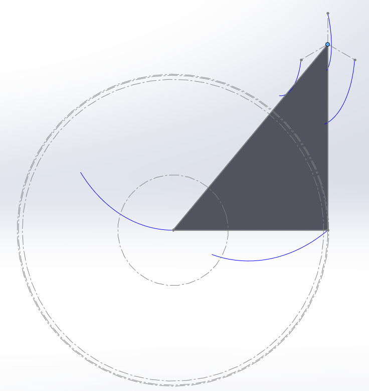
I've completed the math for the tricycle curves. There's are no tangency errors on them.
The direction of the tricycle arms can be translated in any direction and can form any triangle and it will still work, but this looks nice.
Stylus drag pulls the tricycle along nicely as it's all downhill (they share vectors), might be a bit of a problem with records playing from the inside out as the motive force would have to come from the angular contact.
Attachments
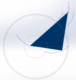

I've completed the math for the tricycle curves. There's are no tangency errors on them.The direction of the tricycle arms can be translated in any direction and can form any triangle and it will still work, but this looks nice. Stylus drag pulls the tricycle along nicely as it's all downhill (they share vectors)
Excellent work! The tricycle idea was suggested years ago in post #19 and #21. It was a crude concept back then and I hadn't refined the idea until recently. Your placement of the 3 points are better and simpler. I just love your graphic skills!
I abandoned the idea due to my stubbornness about not using linear motion bearings and (after all, this is a thread about pivoting genre) thought a parallel tracker would do the same. But you're right about the shared vectors that the stylus drag force pulling the tricycle is much smaller than a parallel tracker. I think this has a lot going for it and easier to use ergonomically as it works just like any pivot arm. The main armwand is similar length to most 9" pivot arms and, for DIYers, it can be salvaged from broken arms and be repurposed to attach it to the tricycle, as long as you take out the 23° offset angle at the bearing. And yes, you can even use magnet to lessen the mass.
The key is to create the 3 curved tracks precisely and make the tricycle moving smoothly with low friction. I'll leave that to the more creative and resourceful members here.
might be a bit of a problem with records playing from the inside out as the motive force would have to come from the angular contact.
People who spend time playing inside out records probably don't care about tangency. 😀
Can this linear slides be used for linear tracking tonearm?
Deltron Precision Linear Slides
These are precision slides with very low coefficient of friction.
They look amazing and I think they definitely have potentials for making linear tonearms.
Stylus drag
Hi 2wice,
There is no doubt that your geometry would result in perfect tracking. However, the force pulling the tonearm along, will have to be controlled by an opposing force. If that is not done, the tonearm will overshoot and the cantilever will be deflected. I have been trying to design a tonearm moved by record fiction for years (since 2010) and I know what you're up against. The drag of the LP acts on the tonearm through a mechanical advantage which increases as the tonearm approaches the label area. That in turn means that the above mentioned opposing force has to increase as the tonearm nears the label area. On top of that, it is not a linear function. It is my opinion, that this problem cannot be solved without some kind of servo, be it mechanical, electronic or magnetic.
Sincerely,
Ralf
Stylus drag pulls the tricycle along nicely as it's all downhill
Hi 2wice,
There is no doubt that your geometry would result in perfect tracking. However, the force pulling the tonearm along, will have to be controlled by an opposing force. If that is not done, the tonearm will overshoot and the cantilever will be deflected. I have been trying to design a tonearm moved by record fiction for years (since 2010) and I know what you're up against. The drag of the LP acts on the tonearm through a mechanical advantage which increases as the tonearm approaches the label area. That in turn means that the above mentioned opposing force has to increase as the tonearm nears the label area. On top of that, it is not a linear function. It is my opinion, that this problem cannot be solved without some kind of servo, be it mechanical, electronic or magnetic.
Sincerely,
Ralf
Hi Ralf
The problem of overshoot did trouble me, and was the reason I abandoned a Unipivot on the same carriage.
The overshoot is constrained by no horizontal bearings coupled to the rigid triangle of the carriage. The geometry solves true for any point in the groove with 3 points on the guide curves. For there to be any overshoot, that triangle will need to deform. I have a preliminary mechanical model where 3 jewel wheels, mounted on that rigid triangle, trace those guide curves. The contact points of the jewel wheels form the rigid triangle.
In simulation I can already see this effect, if I apply a constant force in the -y direction, the wheels bind onto the guide curves. The carriage only starts moving if I change the force vector to the tonearm vector.
I haven't measured it yet but suspect that the bind force on the wheels increases with the deviation of the two vectors linearly.
I do not yet fully understand the effects of the bind force on the wheels, but will have a clear picture once simulations are completed.
It certainly won't be a easy to build, and simulation to successfully implemented not guaranteed.
Last edited:
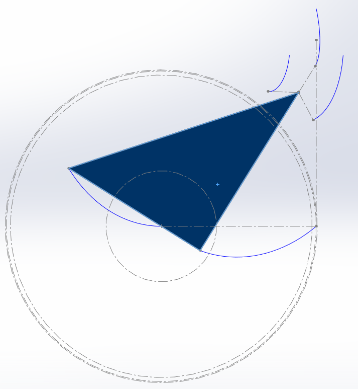
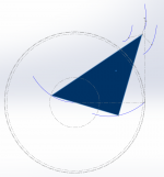
While looking for other triangles that would still solve, I found that removing one of the curves, translating one curve to form a right angle triangle with the stylus as the third point works fine.
This would be easier to built as the sharp curve on the innermost curve was problematic.
On the other hand, overshoot looks like a bigger a problem now, but the arm length can be reduced by another 30 mm.
This would be easier to built as the sharp curve on the innermost curve was problematic.
On the other hand, overshoot looks like a bigger a problem now, but the arm length can be reduced by another 30 mm.
Attachments

directdriver, good to know those bearing can work.
How do linear tonearms cope with bias ? Any Anti skating mechanism worth knowing ?
Regards.
How do linear tonearms cope with bias ? Any Anti skating mechanism worth knowing ?
Regards.
In simulation I can already see this effect, if I apply a constant force in the -y direction, the wheels bind onto the guide curves.
What if the wheels are angled 45° toward the curves instead of vertical, provided the curves are round rods and the wheels have U-grooves?
I found that removing one of the curves, translating one curve to form a right angle triangle with the stylus as the third point works fine.
That does look simpler and easier to build but in your drawing all the tonearm mass is concentrated in the front point/wheel. Is there a graph that places the arm location at the center of the triangle so mass is equally distributed?
The 3 points 2 curve approach reminds me of some curved linear slides.
What if the wheels are angled 45° toward the curves instead of vertical, provided the curves are round rods and the wheels have U-grooves?
I'm thinking 90 Deg wheel running a knife edge along the side of the curve, but your idea would be easier and cheaper. Bending a rod accurately will be a mission though.
That does look simpler and easier to build but in your drawing all the tonearm mass is concentrated in the front point/wheel. Is there a graph that places the arm location at the center of the triangle so mass is equally distributed?
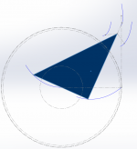
Yes, those curves can be placed anywhere, it will make the arms a little bit longer, closer to a 9". I'll cook something up.
The 3 points 2 curve approach reminds me of some curved linear slides.
Yep, that's what I'd like to do but with 90 deg wheels and magnetic lift.
The tracks can then be lasercut to +-0.25 micron.
Yes, those curves can be placed anywhere, it will make the arms a little bit longer, closer to a 9". I'll cook something up.
To be honest, as a DIYer I prefer the arm to be 9" so I can repurpose existing conventional 9" arms. If arm length is a concern, the curves assembly can be placed ABOVE the arm (yes, a hanging tonearm) and even cantilever slightly over into some record area and you can have an armwand no more than 5 or 6 inches.
Obviously if you want the vertical pivot point located at the record height outside of the (12" type) platter size, then the arm must be longer than 6 inches. With your graphic and geometric skill you can play around with all the permutations and find the optimum geometry.
Something like this?
Unless I'm not seeing correctly, looks like you're missing the third point/wheel of the triangle...
Last edited:
- Home
- Source & Line
- Analogue Source
- Angling for 90° - tangential pivot tonearms