Directdriver, I had already heard of the tonearm of VIV laboratory. I presume it will be a nice tonearm. Probably expensive too. About the ability of a tonearm without fixed pivot to move to a position at right angles to the spindle: the stylus "seeks" equilibrium (the same everage friction at both sites of the stylus). Because the cantilever is damped by rubber, the tonearm will follow this force.
About the ability of a tonearm without fixed pivot to move to a position at right angles to the spindle: the stylus "seeks" equilibrium (the same average friction at both sites of the stylus). Because the cantilever is damped by rubber, the tonearm will follow this force.
I take it your drawing is another form of the Thales geometry?
@directdriver, the Thales tonearm – see picture – is a “fixed” tonearm.
The horizontal movement of the tonearm is forced by the stylus (probably with the help of some magnetic force to lower friction). The geometry – in relation to the joint pivot - is rotating the position/angle of the cartridge/head shell.
In the case of the drifting sphere you can use a straight horizontal bar or a lightly bowed one. Both options will result in a zero tracking angle, so there is quite a big difference in the underlying principle (the Thales tonearm is restricted to geometry).
There is another big difference too: the “sphere tonearm” costs – inclusive silver wiring – about 150 euro. And that’s a bargain for a high end tonearm. I have untwisted the 4 strands in 7 wires each and at the moment the tonearm keeps the right trajectory (see picture). The yellow MM cartridge you see at the image is the cheapest one I could find (about 25 euro). I use it for trying different VT weights (from 1,5 to 3 gram) and mass (from 6 to 16 gram weight for headshell and cartridge). After some adjustments to the wires I will change cartridges (Ortofon MC Cadenza red).
Those clothes-pegs hold the horizontal bar – polished 1,5 mm RVS – and provide easy adjustments to the position of the bar (height) and to take the tonearm off (the horizontal bar is glued only to one clothes-peg). The tin copper wire on the arm tube in front of the sphere is to ground everything so there is no hum from the amplifier (some grains of salt in the water is enough to make the water conductive).
@directdriver, the Thales tonearm – see picture – is a “fixed” tonearm.
Thanks for the elaboration, Tom. I was referring to the Thales geometry as in the Thales semicircle, not Thales the brand of tonearms. In the case of Thales geometry, if you converge the lines of A, B, C, they should meet at a single point which is the corner of one of the three points inside a semi-circle. Thales theorem is that the three points inside a semi-circle will always form a 90º at one corner.
One image flipped to illustrate better.
An externally hosted image should be here but it was not working when we last tested it.

This came from the Birch geometry
An externally hosted image should be here but it was not working when we last tested it.
- - - - - - - - - - - - - - - - - - - - - - - - - -
The horizontal movement of the tonearm is forced by the stylus (probably with the help of some magnetic force to lower friction). The geometry – in relation to the joint pivot - is rotating the position/angle of the cartridge/head shell.
Tom, your floating mechanism makes me think of it as a liquid linear bearing that also allows slight pivoting so it floats in a curved trajectory.
Thanks for the pictures! If you don't mind, I took liberty to link/post it on here.
An externally hosted image should be here but it was not working when we last tested it.
Last edited:
@Directdriver,
There is not so much “geometry” behind the floating tonearm. In the picture below you see the modulated grooves (grey) and the positions of the pivot (blue). A scalable image is here. The size and relations between the concentric circles are caused by the length of the distance between stylus and pivot. Now Imagine we want to draw a concentric circle for all the modulated grooves. That will be impossible, because the groove is winding up. So there are infinite concentric circles.
If there is quite a distance between the pivot points on the concentric circles, we can hear a difference in sound (the frequency is getting lower or higher, what depends on the direction of the moving pivot). Nevertheless, when the distance is something like 0,000.1 mm, it is impossible to hear any “distortion” of the original sound.
So there is hardly geometry, there is an arrangement of correct positions in relation to zero tracking error (stylus at right angles to the spindle). Therefore, the horizontal bar connects infinite concentric circles. It is the stylus/cartridge that have to keep the right angle to connect all those right positions. Therefore, friction have to be limited (this image shows the untwisted silver wiring; to avoid friction between I have rubbed the single wires with silicone oil).
Fixed pivot tonearms are forcing the stylus/cartridge in the desired position. So there are opposite forces that cause resonances and unwanted vibrations. But this “floating tonearm” is seeking the right position by itself. Even the azimuth can be influenced a bit by the stylus. Therefore, you cannot compare this tonearm with any other existing tonearm. It is just another principle.
The next picture shows an Ortofon Cadenza Red cartridge (weights 10,7 gram; 2,5 gram VTF). I have filled half the lower part of the sphere with water to see if the stylus still keeps track. But because of the amount of weight the level of the water was too low. To compensate I added some water but the total weight of the tonearm became a bit too high (the water level was just 1 mm under the edge of the bowl). In the next image I have removed the counterweights and have pushed a carbon tube over the existing tube (the 3 counterweights together weight 10,4 gram). So the tonearm is longer, but the VTF is - of course - still 2,5 gram. Everything was working fine so the right adjustment of the tonearm is not so critical.
There is not so much “geometry” behind the floating tonearm. In the picture below you see the modulated grooves (grey) and the positions of the pivot (blue). A scalable image is here. The size and relations between the concentric circles are caused by the length of the distance between stylus and pivot. Now Imagine we want to draw a concentric circle for all the modulated grooves. That will be impossible, because the groove is winding up. So there are infinite concentric circles.
An externally hosted image should be here but it was not working when we last tested it.
If there is quite a distance between the pivot points on the concentric circles, we can hear a difference in sound (the frequency is getting lower or higher, what depends on the direction of the moving pivot). Nevertheless, when the distance is something like 0,000.1 mm, it is impossible to hear any “distortion” of the original sound.
So there is hardly geometry, there is an arrangement of correct positions in relation to zero tracking error (stylus at right angles to the spindle). Therefore, the horizontal bar connects infinite concentric circles. It is the stylus/cartridge that have to keep the right angle to connect all those right positions. Therefore, friction have to be limited (this image shows the untwisted silver wiring; to avoid friction between I have rubbed the single wires with silicone oil).
Fixed pivot tonearms are forcing the stylus/cartridge in the desired position. So there are opposite forces that cause resonances and unwanted vibrations. But this “floating tonearm” is seeking the right position by itself. Even the azimuth can be influenced a bit by the stylus. Therefore, you cannot compare this tonearm with any other existing tonearm. It is just another principle.
The next picture shows an Ortofon Cadenza Red cartridge (weights 10,7 gram; 2,5 gram VTF). I have filled half the lower part of the sphere with water to see if the stylus still keeps track. But because of the amount of weight the level of the water was too low. To compensate I added some water but the total weight of the tonearm became a bit too high (the water level was just 1 mm under the edge of the bowl). In the next image I have removed the counterweights and have pushed a carbon tube over the existing tube (the 3 counterweights together weight 10,4 gram). So the tonearm is longer, but the VTF is - of course - still 2,5 gram. Everything was working fine so the right adjustment of the tonearm is not so critical.
There is not so much “geometry” behind the floating tonearm. ..... So there is hardly geometry, there is an arrangement of correct positions in relation to zero tracking error (stylus at right angles to the spindle). Therefore, the horizontal bar connects infinite concentric circles.
.....this “floating tonearm” is seeking the right position by itself. Even the azimuth can be influenced a bit by the stylus. Therefore, you cannot compare this tonearm with any other existing tonearm. It is just another principle
I understand what you're trying to accomplish with this purely "passive," floating, approach. Since your cartridge is still attached to something, in the process of finding "equilibrium," the other end of the arm still has geometry involved. As long as you are trying to keep the "stylus at right angles to the spindle" there's geometry to govern the process. It may not be exactly the Thales geometry but it's a variation of the same theme. If you converge all the vertical lines, they will meet at a single point or close to a single point. In the end, your arm is just a segment of the line in the Thales triangle. If the lines don't converge to a single point then something is microscopically off between the gaps, probably inconsequential sonically.
Whatever graphic program you are using, just for yucks, you can try to merge all the lines and you will see that if this is a pivot arm, it will be a very long arm, except this long arm has to extend its length as it gets closer to the spindle. (It's exactly this "extension" that's the obstacle for tonearm designers. Notice the length difference of the two red curved lines on your diagram.) Your design is to eliminate the pivot end of this imaginary pivot arm. If you graph all the lines using the Thales geometry ALL the lines and EVERY position will be 90º to the spindle.
I appreciate the ingenuity of your design. This floating concept can open doors to variations of it using other forms of bearing or movement, such as magnetic levitation, gliding plastic, rollers, airbearing, etc... If you examine member Straight Tracker's thread, his design uses rollers or linear bearings. At least in this type of arm, the traveling length is shorter than typical 4" sliding distance of parallel trackers.
@Directdriver,
It is not Thales, sorry. The crossing points of the vertical lines lie far from each other (far more than the lenght of the tonearm itself).
Your suggestion about variations of this tonearm is a bit curious. Why will people need a complicated expensive tonearm when a simple cheap one outperforms all? So don't expect me to participate in discussions about "semie-technical tonearm designs". When people want to know how they have to construct this "floating tonearm" they can find the details at Exploring Vinyl Audio.
Your suggestion about variations of this tonearm is a bit curious. Why will people need a complicated expensive tonearm when a simple cheap one outperforms all?
I take your point. And, yes, readers interested in this design are highly recommended to check out Tom's website.
While cost is a factor for DIYers but a lot of it is for fun factor. Personally I just enjoy tonearm designs for design sake therefore this thread is purely for discussion and entertainment, not a step by step construction thread. Of course it can be if any member wants to contribute ideas. I just want to add that since this thread is named "tangential pivot tonearms," the focus is on the genre. There's another thread on "mechanical linear tonearm" or similar threads in the forum.
If the friction between the horizontal and the vertical bar is high, the tonearm pivots and can not follow the needle gliding along the horizontal bar. If the friction is low, the tonearm must have a tendency to align itself at right angle to the horizontal bar. Am I wrong?
@alighiszem,
No, you are right. The right movement of the tonearm is not restricted to friction only. Because zero tracking error – inclusive a non-rotating tonearm – can only be archived by a real linear movement of the tonearm (the so called tangential tonearm).
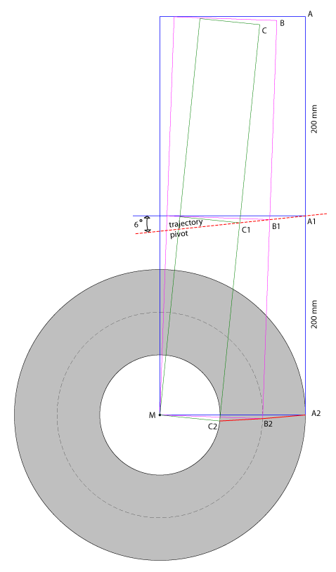
In the case of the floating pivot tonearm the trajectory of the stylus and the trajectory of the pivot/sphere are not identical. Therefore, there have to be a rotating of the pivot/sphere to keep zero tracking error. The first image shows the rotation by the lines B-B2 and C-C2 and it is clear that the stylus is at right angles to the spindle all along the trajectory. (In the case of a tonearm with a fixed pivot these forces are called "skating" and are caused by overhang and underhang of the stylus in relation to the spindle.)
The rotating of the tonearm is caused by the average friction of the rotating groove. So it is this force that aligns the tonearm at right angles to the spindle all along the trajectory (see this image).
The tonearm will not move when the friction is too high. And... the tonearm will only move in one direction, because the rotating groove pulls at the stylus by the tracking weight (no tracking weight – no pull).
When the floating sphere moves too fast, the sphere cannot stop and move back. But it is possible to lower the speed of the sphere by choosing the right diameter of the vertical bar (the red circle in the image).
There is an optimum for the friction of the moving sphere, in relation to the angle of the horizontal bar. This optimum can be obtained by the correct diameter of the vertical bar and by an identical angle between the vertical and horizontal bar at every point of the trajectory of the sphere. So we have to bent the horizontal bar a bit. The next image shows the result/construction for an angle of 3 degrees.
Unfortunately, the vertical tracking weight determinates the friction between the horizontal bar en the vertical bar. Therefore, a phono cartridge with a tracking weight of 2,5 gram needs a horizontal bar with an angle of about 5 degrees. So this horizontal bar have to be bent a little bit more.
No, you are right. The right movement of the tonearm is not restricted to friction only. Because zero tracking error – inclusive a non-rotating tonearm – can only be archived by a real linear movement of the tonearm (the so called tangential tonearm).
In the case of the floating pivot tonearm the trajectory of the stylus and the trajectory of the pivot/sphere are not identical. Therefore, there have to be a rotating of the pivot/sphere to keep zero tracking error. The first image shows the rotation by the lines B-B2 and C-C2 and it is clear that the stylus is at right angles to the spindle all along the trajectory. (In the case of a tonearm with a fixed pivot these forces are called "skating" and are caused by overhang and underhang of the stylus in relation to the spindle.)
The rotating of the tonearm is caused by the average friction of the rotating groove. So it is this force that aligns the tonearm at right angles to the spindle all along the trajectory (see this image).
The tonearm will not move when the friction is too high. And... the tonearm will only move in one direction, because the rotating groove pulls at the stylus by the tracking weight (no tracking weight – no pull).
When the floating sphere moves too fast, the sphere cannot stop and move back. But it is possible to lower the speed of the sphere by choosing the right diameter of the vertical bar (the red circle in the image).
There is an optimum for the friction of the moving sphere, in relation to the angle of the horizontal bar. This optimum can be obtained by the correct diameter of the vertical bar and by an identical angle between the vertical and horizontal bar at every point of the trajectory of the sphere. So we have to bent the horizontal bar a bit. The next image shows the result/construction for an angle of 3 degrees.
Unfortunately, the vertical tracking weight determinates the friction between the horizontal bar en the vertical bar. Therefore, a phono cartridge with a tracking weight of 2,5 gram needs a horizontal bar with an angle of about 5 degrees. So this horizontal bar have to be bent a little bit more.
Last edited:
Sorry alighiszem,
I had edited the text but didn’t noticed I made a mistake (now it is quite puzzling).
The sentence “In the case of a tonearm with a fixed pivot these forces are called "skating" and are caused by overhang and underhang of the stylus in relation to the spindle.” must come behind “The rotating of the tonearm is caused by the average friction of the rotating groove. So it is this force that aligns the tonearm at right angles to the spindle all along the trajectory (see this image).”
New Tonearm: Thales Easy
I like the trend that Thales is going with their tonearm design. They're simplifying the construction and lowering the price. Very unique design. Using only a single main armwand must cut the cost down significantly. I also like the look of it.
I like the trend that Thales is going with their tonearm design. They're simplifying the construction and lowering the price. Very unique design. Using only a single main armwand must cut the cost down significantly. I also like the look of it.
An externally hosted image should be here but it was not working when we last tested it.
An externally hosted image should be here but it was not working when we last tested it.
An externally hosted image should be here but it was not working when we last tested it.
Thales Easy: how do they handle anti-skating, when the offset is constantly varying from positive at the start, to zero in the middle, then negative at the end of an LP?
B-J reborn
You're right that it's really a modern version of the Burne-Jones tonearm. When I first looked at the pictures, I thought it's a cheaper version of their Simplicity model as that's how I would prefer the Simplicity is built using the tetragon geometry with the construction of the Easy which can be implemented into many existing tonearms, vintage and new. It has more DIY potential...
I supposed if they build the Easy using Simplicity geometry that it has the potential for awkward marketing if the Easy outperforms the Simplicity! Who comes up with these silly model names?!
Thales Easy: how do they handle anti-skating, when the offset is constantly varying from positive at the start, to zero in the middle, then negative at the end of an LP?
I have no idea and I agree with your observation. It doesn't appear to have an antiskating device at all. The idea of setting the zero point in the middle of the record seems to follow the camp of tonearms by RS Labs and Viv Labs Rigid Float that they concern more about lessening skating force than tangency. But they don't seem to address the consistency of skating force across the entire record though as it starts underhang to zero and back to underhang again.
I look forward to seeing more pictures and explanations once the Easy is officially released.
.
With these arms using mobile geometry to chase the "holy grail" of tangential tracking.
I do wonder if people are loosing more with any slack and movement in the linkages than the gain on tracking geometry?
The linkages must be free moving as they are only connected via the stylus to the record. But does this slack degrade reproduction?
What are the trade offs?
I do wonder if people are loosing more with any slack and movement in the linkages than the gain on tracking geometry?
The linkages must be free moving as they are only connected via the stylus to the record. But does this slack degrade reproduction?
What are the trade offs?
Thales Easy: how do they handle anti-skating, when the offset is constantly varying from positive at the start, to zero in the middle, then negative at the end of an LP?
But Shirley, there shouldn't be any need for antiskating in a parallel tracker?
Cheers Steve
ohh but there is, the reason for the anti-skating is not the tracking error, but the fact that there's is an offset angle to the grove angle, this makes the cart pull in a direction different to that of the bearing point of the arm, in case of the Thales the skating forces change direction while the cartridge plays the record only in the middle of the track-band are the skating forces zeroed out. I am sure there's is some kind of skating compensation built into the arm, as it varies from negative to positive, the ordinary weight system can not be used.
I do wonder if people are loosing more with any slack and movement in the linkages than the gain on tracking geometry?
The linkages must be free moving as they are only connected via the stylus to the record. But does this slack degrade reproduction?
What are the trade offs?
I'm with ColinA here. Hearing a good unipivot, and knowing that the cause of beeing good, comes down to the minimum number of "joints" in the design, must lead to the notion that there are trade offs in a system thad needs 6 or more bearings. Regarding antiskating, or the loss of it, my skills are not as good as I could wish for, but my 12 inch Ortofon arm has also no antiskating system, and it works flawlessly in spite of that.
Steen
But Shirley, there shouldn't be any need for antiskating in a parallel tracker?
Shirley is not here but I would respond that as member Conrad Hoffman once pointed out in a post that if the stylus/cantilever and the main pivot does not form a straight line, there will always be some skating force. The Thales might lessen skating force but it still exists.
I am sure there's is some kind of skating compensation built into the arm, as it varies from negative to positive, the ordinary weight system can not be used.
I think the Easy arm is a good candidate for using a dual magnet antiskating system, that is, one magnet to repel the inner groove and one for the outer groove sort of like the Italian Morsianiunipivot tonearm and since the Easy is not unipivot it's easier to control lateral forces. The middle groove has zero force of course. Judging by the Thales picture I doubt there's any antiskating and perhaps the designer decided the skating forces are negligible to include it. We'll find out when more info is available.
- Home
- Source & Line
- Analogue Source
- Angling for 90° - tangential pivot tonearms