When an amp with zero impedance drives a load of say, 4 ohms through a 20 foot long cable with a characteristic RF impedance of say, 150 ohms (bog standard zip cable), the time it takes for the load current to be what the amp is trying for can go into tens of microseconds. That is a consequence of the cable storage mechanism.That was exactly the point I tried to make when showing those graphs.
Our auditory system is so complex that so far no one could come with a explanation why cables have differents sounds.
I have seen so many different theories that I just don’t read them anymore.
It was the characteristic impedance story that catched my eye were I could not resist to prove that is was just another fairy tale.
Hans
When the load is far below the cable impedance, the storage mechanism is inductance. When the load is far above the cable impedance, the storage is capacitive.
I put some of this in my gallery some years ago..2014, to be exact.
What most do not consider is: as a speaker is accelerating, it's dynamic impedance is changing. If left and right speakers are accelerating at different rates (which they should given that it's stereo), they will provide different impedances to other frequencies. When the impedance changes the settling time (or transient delays), that will impact imaging if it exceeds human ITD thresholds (roughly 2 to 5 microseconds).
I've considered how to measure the dynamic impedance of a driver at a specific frequency while pushing it very hard at another, but the number of confounders is exceedingly high. It would require making a voice coil with high strandcount litze, and all the magnetic circuit with high frequency ferrite or thin lamination iron (edm slots at the inner surface of the front plate of course). The eddy/proximity issues are rather daunting.
Oddly enough, the high level motion control gurus are starting to understand this concept, although they have yet to understand it completely. They are still in the learning throes.. One guy thinks the PWM amplifier changes bandwidth with power/current level.. at least he's trying..hopefully he will revisit the magnetic portion of the motors, to understand the dynamics of magnetic field forces.
As to speaker cables, given the range of dynamic impedance, I long ago settled into a useful value of 25 ohms RF Z in order to reduce the system settling time variance to a minima without worrying about the amp driving a really capacitive load. All it takes is 4 zip pairs, say #18 awg, each twisted to some pitch, all four different. And, I mean bog cheap zip, nothing exotic.
jn
Last edited:
...in a TV studio with analog video that passed thru 75 ohm cable impedance matching was very important. As I remember analog video (NTSC) goes down to around 30 cycles. This would be considered an audio frequency....
But did you ever see Improper Termination? On a short line you only have the expected 6dB rise of level. On a studio-width line you have ghost/echos at sudden changes of image lightness. Perhaps 1/100th of a screen width, so over 1MHz.
That's for the extreme cases. For mild change of impedance the trouble is even less.
Ohh.... we gotta be critical, when we read stuff like this 😉
Quickly I notice a few things that makes me dig deeper.
The video is heavily distorted and tries to show an extreme difference between two cables - which is simply so huge, that something has to be wrong.
So that makes me think that they tried to boost the volume from a very weak signal, to try an emulate a huge difference, that would practicaly never be there to begin with.
If an amplifier has problems with a few meters of wire.... it's broken or stupidly bad designed... get another one. If the speaker represent a too complex load.... again.... get another one.... it's simply not needed and we should all help each other to make such bad designs - go extinct. Especially seen in the light of the price of some of these cables.
Just read some of the comments below tha article.
They clearly explain that you may only loose around 0,4 dB at 20KHz - and absolutly not 10 dB or so.
Lets just quote some of them:
"– Figure 3 db scale is not correlated to any actual value."
"– Appendix B: Isolda listed as 6.6uh for 7m, but is listed on Townshend website as 0.002uH (for 2m?). 0.002 is very wrong. I suspect 6.6uH is considerably off."
"– Appendix B: Method-1 does not give an accurate method for characteristic impedance. The meter cannot isolate L from C so this does not work. (It is also a really poor quality meter)"
"A 7m cable with a propagation is 5nsec/m (typical) will have 714 reflections in 5usec (20KHz). Using worst case transmission line reflections, the error at 20Khz due to transmission line effects is thousands of db below the signal level. Think about -4300db. We have a hard time with -100db in relation to the signal let alone -4300db."
From this article - I have now lost all respect - if anything left in total - for PS Audio.
They build some nice looking gear, but this is just a very sad attempt to sell BS cables.
Pheeew 😀 I know I come off as a bitter old man... but geeez... gotta let out some steam on these silly claims 😎
"From this article - I have now lost all respect - if anything left in total - for PS Audio"
The opening of identical blank envelopes was enough for me
The opening of identical blank envelopes was enough for me
The references that you provide amplify once more my feeling that you have no idea what you are talking about.Telegrapher's equations is what comes to mind (not the simplified version limited to the reactive terms)
Telegrapher's equations - Wikipedia
You can also have a look at impedance data provided by reputable cable manufacturers, like Huber-Suhner, etc
You can also look here, in particular at the graph:
Nominal impedance - Wikipedia
Sorry, it originates from French :lineic - Wiktionary
It just means a parameter (inductance, capacitance, resistance or whatever) per unit of length.
Anyway, the best way to test the validity of your model is to cascade a number of sections: Zo should remain invariant whether you have 1, 10, 100 or more sections.
Ultimately, if you cascade enough sections, you do not even need to go through the sqrt(....) etc: just plot Vin/Iin, it will yield the Zo for an infinite TL
Bidirectional communication over a telephone line comparing to driving a LS, you must be kidding.
But even there they show a Ch. Imp. graph going as low as 10Hz, also nonsense?
And your piece wise cascading theory is really amusing.
So, thank you for your contribution.
Hans
Theory is general, and applies equally to any transmission line; numerical values may be different, but the overall behaviour remains similar.
A typical twisted pair has a Zo of around 100ohm.
If you add more copper, you will lower that impedance: it can be likened to paralleling a number of lines. With 10 pairs, you will reach 10ohm, but the behaviour will remain fundamentally the same, apart from a scale factor of 10.
It is perfectly possible to measure Zo at 10Hz, or even lower, but the magnitude will be very different from the HF one, much larger in fact.
As this is not reproduced in your sims, it can only mean one thing: the modelling is flawed.
With copper, it is impossible to maintain a flat Zo at low frequencies. You would need superconductors to achieve that.
Some more material:
Char. Impedance
As for cascading, it offers a simple and reliable means of sanity check: for a given type of cable, Zo is an invariant. For a 50ohm cable, it doesn't matter whether it is 1m, 10m or 100m, it will remain 50ohm.
To check the validity of your model, you simply need to duplicate the sections. If the curves keep the same look with more than one section, then your model is correct.
To model the effect of a speaker cable on the losses, FR, etc, a simple lumped model is perfectly sufficient.
Computing Zo using the geometric average formula is perfectly legit for transmission lines.
However, this does not imply that using the formula on something which is in fact not a transmission line, is correct
With superconductors, you only remove R, but not G. At 4.5K, kapton, nomex, and tefzel are the only practical insulators, they have a relative permittivity around 2.7.
Supers also skin totally. A single round conductor will run current on the outer portion of the super, at the critical current density. If for example, your wire has a critical current density of 1000 amps per square mm, at 1000 amps the wire will have current only on the outer section of the wire using exactly 1mm of the section. As current goes up, more of the wire is used until the current uses all the cross section, then it will quench.
Using a single LC pair in an analysis is not the same as TL, as Elvee points out. Increasing the number of elements eventually gets the model to stabilize. IIRC, Cyrus used 200.
If a step input is pushed through a single LC model, the slew rate is limited by the inductance feeding a capacitance. As the number of elements increases in the model, the step response will approach reality. If the line and load match, the step response at the load will be identical to the amp output, just delayed a very small bit.
If the load is much lower than the line, the line has to magnetically charge, requiring many transits of the signal.
Any talk about FR is fairly useless given reasonable cables. Consider the settling time of the system instead.
Jn
Last edited:
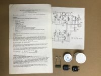
Just as a little light relief:
Back in the 1960s, Rogers were aware of the possibility of RF pickup in loudspeaker cables and suggested a (questionable) solution.

Back in the 1960s, Rogers were aware of the possibility of RF pickup in loudspeaker cables and suggested a (questionable) solution.
Simple, happy, carefree days!"Under some conditions trouble may be experienced from radio breakthrough.
In such cases it will often be found that using television co-axial lead for the speaker wiring instead of twin-flex will effect a complete cure."
Attachments
What part of 16 gauge zip cord do you not understand? 😀 It's darn near perfect. I guess if you have money left over from that $30,000 DAC, might as well.
PS somehow went from a highly respectable amplifier builder to a supplier of snake oil.
PS somehow went from a highly respectable amplifier builder to a supplier of snake oil.
I found this article interesting as it shows measurement to try to explain the differences in speaker cables.
The “Sound” of Speaker Cables: an Analysis | PS Audio
Oh my goodness, I just looked at the paper. Boy, did they blow it...
The test measurement setup is bad. Once that is realized, the entire premise falls apart.
They formed a ground loop between the speaker return wire and the measurement inputs. While they think they are simply measuring IR drop, they are also measuring the induced voltage caused by the current slew.
When the two conductors are close together, the magfield of the two wires try to cancel. When the conductors are moved farther apart, the ground loop picks up more signal.
By design, this test setup can only reinforce the premise that close is good, apart is bad.
I cannot say if the test was cherry picked to reinforce a specific conclusion, or if they did not understand what they were doing.
They really should have just used an interleaved zero inductance CVR at the amp return terminal.
Jn
I have always used 13 amp mains stranded cable for speakers both low and high power.
I ran a mobile disco for 40 years and never had any complaints about sound except maybe too loud !
I ran a mobile disco for 40 years and never had any complaints about sound except maybe too loud !
Oh my goodness, I just looked at the paper. Boy, did they blow it...
The test measurement setup is bad. Once that is realized, the entire premise falls apart... I cannot say if the test was cherry picked to reinforce a specific conclusion, or if they did not understand what they were doing.
I can. 😉 As noted, it's neither a paper, nor a writeup of research work: it's an infomercial. This article was written by Max Townshend, of Townshend audio, who just happen to sell expensive wire of the type advocated here.
As it happens, I've briefly met Max at shows a couple of times, and I've no personal problem with him -he seems a nice enough bloke, and he has my respect for maintaining a viable business in a very competitive market.
Last edited:
It's possible. However, many people simply do not have an understanding of how magfield coupling works. I've seen it time and time again. Just look at ground loop issues, they are all over the place.
While I tend to concur with the overall theme that using a cable which matches the load is best, I do not approve of a flawed test which cannot refute the hypothesis due to a methodology flaw.
Since speakers do not have a single impedance value over the entire spectrum, I still recommend a Z of roughly 25, which is consistent with 4 paralleled twisted pair zips, #16 would be my choice for medium power, #24 would suffice in my home. And, really cheap zip, like off the shelf home depot stuff.
Running 4 or 8 ohm RF Z cables requires a Zobel for safety. A 25 ohm RF z does not, as it won't store anywhere near as much capacitive energy as the 4 or 8 when the speaker unloads at high frequency.
jn
Last edited:
Why not just try some different speaker cable constructions and find out if any sound different. If they do, then there is some basis for further investigation.
IME, its more than simply Zo that can have an audible effect. When correlating affected sound with cable construction, some things that can be causal factors are pretty easy to grok, others may take more effort.
IME, its more than simply Zo that can have an audible effect. When correlating affected sound with cable construction, some things that can be causal factors are pretty easy to grok, others may take more effort.
Just as a little light relief:
Back in the 1960s, Rogers were aware of the possibility of RF pickup in loudspeaker cables and suggested a (questionable) solution.
Simple, happy, carefree days!
Coax speaker cable is an option, why is it used?
Well, using a step is a completely different way of finding the Char. Imp. Zo, but that was not at all what that I did.Using a single LC pair in an analysis is not the same as TL, as Elvee points out. Increasing the number of elements eventually gets the model to stabilize. IIRC, Cyrus used 200.
If a step input is pushed through a single LC model, the slew rate is limited by the inductance feeding a capacitance. As the number of elements increases in the model, the step response will approach reality. If the line and load match, the step response at the load will be identical to the amp output, just delayed a very small bit.
If the load is much lower than the line, the line has to magnetically charge, requiring many transits of the signal.
Jn
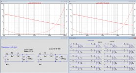
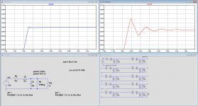
When using the AC analysis, it makes no difference whether you take one element or N.
See the example below for 1 and for 10 elements with the calculation Zo=sqrt(Zopen*Zshort). There is absolutely no difference between the two.
Now look at the second image where a 1V square wave is offered to resp 1 and 10 segments of the Townshend cable, here terminated with 8R.
Now you see a large difference in overshoot and settling between the two.
When trying to find the the Char Imp with this Step method, you will indeed have to cascade many elements, I would not have argued against that.
But to avoid all that, that's why I used the much more convenient way to determine Zo.
Hans
Attachments
I was following the older JN’s technical wire correspondence.
I had filed the IMO important parts. I’ve saved them (Oct2006 to Jan 2014)
Dropbox - jneutron on cables 2006-2014.pdf - Simplify your life
George
I had filed the IMO important parts. I’ve saved them (Oct2006 to Jan 2014)
Dropbox - jneutron on cables 2006-2014.pdf - Simplify your life
George
It's possible. However, many people simply do not have an understanding of how magfield coupling works. I've seen it time and time again. Just look at ground loop issues, they are all over the place.
While I tend to concur with the overall theme that using a cable which matches the load is best, I do not approve of a flawed test which cannot refute the hypothesis due to a methodology flaw.
Quite so. And neither do I (approve) -I just don't consider it to be a test, just a website article / infomercial written in a pseudo-technical style with the object of promoting the manufacturer's product. The PS audio website editor even helpfully leaps in with a note of his own in the (ahem) 'Abstract' pointing out that the author's company produces just such a wire as the article advocates, lest anybody be an any doubt from whom they can purchase such a product. 😉
Last edited:
But as they say, "There's a sucker born every minute." and boutique audio cable business still exists.Ya just hook the damn speakers up with sensible copper wire of the right size, and enjoy the music.
Don't make yourself nuts over nothing.... nothing that a human can hear.
Please share the setup details on listening to different speaker cable constructions. Is it double blind, single blind, sighted, quick switching, slow switching, duration of listening...etc.? Details matter.Why not just try some different speaker cable constructions and find out if any sound different. If they do, then there is some basis for further investigation.
IME, its more than simply Zo that can have an audible effect. When correlating affected sound with cable construction, some things that can be causal factors are pretty easy to grok, others may take more effort.
Good idea, tell me where I can get some free samples.Why not just try some different speaker cable constructions and find out if any sound different. If they do, then there is some basis for further investigation.
- Status
- Not open for further replies.
- Home
- General Interest
- Everything Else
- Analysis of speaker cables