I don't buy the transmission line theory idea at all for audio cables. Wavelengths are way too long for living room length cables, and there is no impedance matching at the cable ends using amplifiers & speakers. They are just wires carrying a relatively low frequency AC. If cable capacitance causes a change in sound, then maybe the amplifier is not up to the task and needs remediation.
I don't buy the transmission line theory idea at all for audio cables. Wavelengths are way too long for living room length cables, and there is no impedance matching at the cable ends using amplifiers & speakers. They are just wires carrying a relatively low frequency AC. If cable capacitance causes a change in sound, then maybe the amplifier is not up to the task and needs remediation.
It is a tad more complex than that.
Since I elaborated a bit over a decade ago here...I will not repeat.
Jn
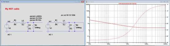
Just out of curiosity, I measured my speaker cables and plotted the characteristic impedance just like I did for the Townshend cable.
Capacity and resistance values are quite accurate, but inductance might be a bit less accurate.
But as a first indication, it comes even closer to the Zo = 8R than the Townshend cable.
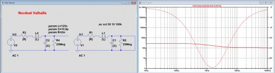
Then I made a Sim of the very expensive but highly praised Nordost Valhalla LS cable.
This one doesn't even come close to the Zo = 8R, but it's impedance is remarkably flat.
So to conclude, I don't think there is enough evidence that the characteristic impedance theory is the holy grail to explain sound differences.
Hans
Capacity and resistance values are quite accurate, but inductance might be a bit less accurate.
But as a first indication, it comes even closer to the Zo = 8R than the Townshend cable.
Then I made a Sim of the very expensive but highly praised Nordost Valhalla LS cable.
This one doesn't even come close to the Zo = 8R, but it's impedance is remarkably flat.
So to conclude, I don't think there is enough evidence that the characteristic impedance theory is the holy grail to explain sound differences.
Hans
Attachments
It is important to understand the energy storage within the cable.
When the inductive and capacitive storage are equal, the cable z matches the load and the response delay is a minima.
Because speaker loads are so variant, I recommend a cable "RF" impedance close to 25 ohms. That is a good tradeoff between response time and the capacitive load seen by the amp when the speaker unloads at frequencies within the amplifier's unity gain frequency... otherwise, you may need a zobel.
Jn
Last edited:
It is also important to consider the frequency at which the cables are measured. Even bog standard zip cord (figure 8 cord) has a frequency dependent inductance within the audio band. As well, flat conductors will skin to the edges, or if side by side, proximity as a result of the wildly varying reluctance path.
Jn
Jn
Estimating the characteristic impedance from a single LRC section is completely wrong at low frequencies..Just out of curiosity, I measured my speaker cables and plotted the characteristic impedance
To do that, you would need to cascade hundreds of elementary sections, and the result would be completely different.
Basically, below the Zo cutoff frequency, Zo increases (up to infinity at very low frequencies), and tends to adopt a 45°, capacitive phase.
The cutoff frequency is R/(2*Pi*L), R and L being the lineic parameters, and is around 2.5kHz for the two examples provided.
At lower frequencies, the magnitude will become increasingly large.
The situation is somewhat complicated by the inductance variation effects hinted by JN, but they are relatively minor and will further increase the LF Zo
I’m always getting a bit irritated by postings that are talkings things into the ground without any evidence or mathematical prove to substantiate.
And yes, JN is right that L and C may vary but within the audio range I don’t expect large deviations.
Zo = sqrt(Zopen*Zshort) is a mathematical correct expression.
So despite of a limited variation in L and C, it’s good enough to prove that the Townshend claims are to be taken with very big corns of salt.
Hans
The expression is perfectly correct from a mathematical POV, but like any tool it has to be used in a proper and meaningful context.Zo = sqrt(Zopen*Zshort) is a mathematical correct expression.
A way to check the validity of your model is to apply your (perfectly correct) formula to a different number of sections, in your case it can only be >1.
If the formula actually yields a characteristic impedance (in the transmisssion lines theory context), you can cascade any number of sections and still get the same result.
This can be done by just multiplying your initial cell by n, in which case the LF value will become increasingly accurate, or you can split the lineic components into smaller parts, which will increase the HF accuracy of the model.
Ideally, if you want a good overall accuracy from LF to HF, you need to do both: increase the granularity and the total simulated length.
With your sim, you can just cascade sections from 1 to n and see that the LF characteristic impedance increases, and the phase tends to 45°.
If you have a sufficient number of sections, the transition from a flat, resistive impedance will happen at ~2.5kHz.
Lumped models are always approximations of distributed systems, and with the lump=1, you have to expect the crudest approximation possible.
In an audio context, the concept of characteristic impedance should generally be avoided, because it is highly misleading (it does exists, and has a meaning, but it is certainly not the one most people think it is)
Last edited:
A reference to some authoritive paper would be welcome.The expression is perfectly correct from a mathematical POV, but like any tool it has to be used in a proper and meaningful context.
A way to check the validity of your model is to apply your (perfectly correct) formula to a different number of sections, in your case it can only be >1.
If the formula actually yields a characteristic impedance (in the transmisssion lines theory context), you can cascade any number of sections and still get the same result.
This can be done by just multiplying your initial cell by n, in which case the LF value will become increasingly accurate, or you can split the lineic components into smaller parts, which will increase the HF accuracy of the model.
Ideally, if you want a good overall accuracy from LF to HF, you need to do both: increase the granularity and the total simulated length.
With your sim, you can just cascade sections from 1 to n and see that the LF characteristic impedance increases, and the phase tends to 45°.
If you have a sufficient number of sections, the transition from a flat, resistive impedance will happen at ~2.5kHz.
Lumped models are always approximations of distributed systems, and with the lump=1, you have to expect the crudest approximation possible.
In an audio context, the concept of characteristic impedance should generally be avoided, because it is highly misleading (it does exists, and has a meaning, but it is certainly not the one most people think it is)
So far it’s nothing but words.
Hans
P.S. Even Wiki doesn’t know what a lineic compoment is.
With all DUE respect, any of these "speaker wire discussions" that I've come across on various audio sites doesn't really even amuse me anymore.
They use to make me smile, even laugh...
Because despite all those so-called authorities and their blabber over wire and audio frequencies, it's all nothing more than just that..... blabbering.
Ya just hook the damn speakers up with sensible copper wire of the right size, and enjoy the music.
Don't make yourself nuts over nothing.... nothing that a human can hear.
Telegrapher's equations is what comes to mind (not the simplified version limited to the reactive terms)A reference to some authoritive paper would be welcome.
So far it’s nothing but words.
Telegrapher's equations - Wikipedia
You can also have a look at impedance data provided by reputable cable manufacturers, like Huber-Suhner, etc
You can also look here, in particular at the graph:
Nominal impedance - Wikipedia
Sorry, it originates from French :lineic - WiktionaryP.S. Even Wiki doesn’t know what a lineic compoment is.
It just means a parameter (inductance, capacitance, resistance or whatever) per unit of length.
Anyway, the best way to test the validity of your model is to cascade a number of sections: Zo should remain invariant whether you have 1, 10, 100 or more sections.
Ultimately, if you cascade enough sections, you do not even need to go through the sqrt(....) etc: just plot Vin/Iin, it will yield the Zo for an infinite TL
With all DUE respect, any of these "speaker wire discussions" that I've come across on various audio sites doesn't really even amuse me anymore.
They use to make me smile, even laugh...
Because despite all those so-called authorities and their blabber over wire and audio frequencies, it's all nothing more than just that..... blabbering.
Ya just hook the damn speakers up with sensible copper wire of the right size, and enjoy the music.
Don't make yourself nuts over nothing.... nothing that a human can hear.
That was exactly the point I tried to make when showing those graphs.
Our auditory system is so complex that so far no one could come with a explanation why cables have differents sounds.
I have seen so many different theories that I just don’t read them anymore.
It was the characteristic impedance story that catched my eye were I could not resist to prove that is was just another fairy tale.
Hans
Characteristic impedance is indeed a fairy tale for audio (except long POTS telephone lines), only lumped parameters matter, but if you discuss Zo, you should do it properly.
Which is why the subject is best avoided.
The much regretted David (DF96) would have had a lot to say about the subject
Which is why the subject is best avoided.
The much regretted David (DF96) would have had a lot to say about the subject
When I worked in a TV studio with analog video that passed thru 75 ohm cable impedance matching was very important. As I remember analog video (NTSC) goes down to around 30 cycles. This would be considered an audio frequency and the whole 20-20K audio range will pass thru a video distribution amplifier. If matching is important in analog video at its frequencies maybe it is worth considering in our audio speaker cables. The measurements in the link I posted at the beginning of this thread do seem to show something real.
ΞTRON(R) Demonstration - YouTube
Here is a video from Shunyata showing their square wave measurements of a speaker cable and their method of improving it. Could it be RC networks?
Here is a video from Shunyata showing their square wave measurements of a speaker cable and their method of improving it. Could it be RC networks?
- Status
- Not open for further replies.
- Home
- General Interest
- Everything Else
- Analysis of speaker cables