Why do you get a sinc that belongs to 2Fs when you have two DACs running on 1Fs? Or is this about normal oversampling rather than the post #258 thing?
Of those 176.4 million multiplications, 132.2 million will be multiplications with the stuffed zeros.
For the record, it should be 132.3 million multiplications with the stuffed zeros, of course.
Why do you get a sinc that belongs to 2Fs when you have two DACs running on 1Fs? Or is this about normal oversampling rather than the post #258 thing?
Marcel, when you take a look at the .asc file that Hayk made available, there is in fact only one Dac, equipped with a multiplexer in front that is switching at 2Fs between the (delayed) direct samples taken at Fs and the midway samples from the convolution filter also working at Fs.
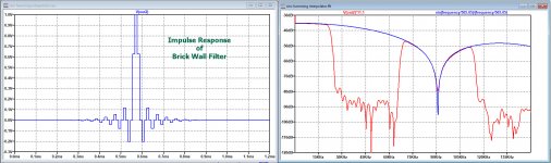
When sending an impulse through this chain, because of the multiplexer it looks as if all data goes through the filter with 2Fs, with data stuffed with a zero after each sample and a filter made twice a long with additional zero's.
This could very well have been the case, but here it is absolutely not what was done. The result however would have been the same.
So the multiplexer is doing a perfect job and is the only component working at 2Fs.
Hans
So this is plain old two times oversampling with digital filtering and polyphase decomposition. OK, got it!
SAA7220 Datasheet(PDF) - NXP Semiconductors
If you want only two times oversampling, you can decimate its output (throw away every other sample).
I don't know if any of its polyphase decompositions consists of a series of zeros, a 1 and another series of zeros, as would be needed to meet your requirement of sample sacredness. More recent chips often use half-band filters, those should meet it.
Marcel,
It’s nice to see how inventive they where with restricted amount of rom and ram.
But just one half band filter such as Hayk used restricts flexibilty of the filter choice, doesn’t it?
Hans
It’s nice to see how inventive they where with restricted amount of rom and ram.
But just one half band filter such as Hayk used restricts flexibilty of the filter choice, doesn’t it?
Hans
Increasing the midpoint gain by 15%, I get minimum image at -36db and -1db for 20khz.

SAA7220 looks to be low pass filter rather than interpolator. I don't see how I can make it produce only the midpoints to multiplex with the sacred samples to be left untouched.
The interpolator it contains is used to replace defective samples by linear interpolation before it passes low pass filters to have the image eliminated. Mine has no any filtering just interleaving the sacred samples by sinc/Hamming interpolated mid levels. I don't see any resemblance.
Last edited:
Hayk,
You still don’t seem to understand the whole picture.
Your halve band filter is just a smart execution of zero stuffing and processing with a filter twice as long filled with alternative n/2 zeros exept a 1 in the middle.
You can’t increase the gain of the midband filter, that ruins the whole interpolation.
How do you make your FFT’s, they are wrong.
You should use the .asc file I sent in #320.
Yours had several failures that I corrected for you.
And let Marcel respond to the SAA, because here you are also not in the right track.
Hans
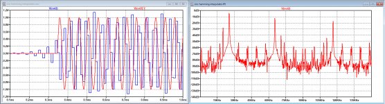
Here is what you get when increasing the mid band samples by 15%.
The mid band samples no longer fit the input signal and the spectrum shows a huge peak at 25.45Khz.
Compare this to the image in #320 !
Hans
The mid band samples no longer fit the input signal and the spectrum shows a huge peak at 25.45Khz.
Compare this to the image in #320 !
Hans
Attachments
Last edited:
I don't see what is modified in your asc file. I don't see neither any stuffing of 1's instead of zero's as you do, I don't see neither any filtering I am doing to be associated with low pass filtering. All I am doing is sinc interpolation to harvest mid sample values and merge to the original. My approach is in time domain, low pass filtering is in frequency domain.Hayk,
You still don’t seem to understand the whole picture.
Your halve band filter is just a smart execution of zero stuffing and processing with a filter twice as long filled with alternative n/2 zeros exept a 1 in the middle.
You can’t increase the gain of the midband filter, that ruins the whole interpolation.
How do you make your FFT’s, they are wrong.
You should use the .asc file I sent in #320.
Yours had several failures that I corrected for you.
And let Marcel respond to the SAA, because here you are also not in the right track.
Hans
Why I don't have the 25khz peak?Here is what you get when increasing the mid band samples by 15%.
The mid band samples no longer fit the input signal and the spectrum shows a huge peak at 25.45Khz.
Compare this to the image in #320 !
Hans

Attachments
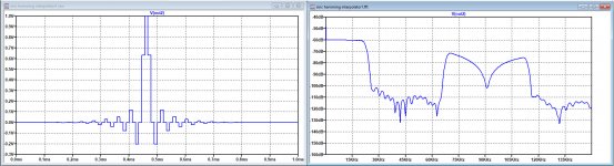
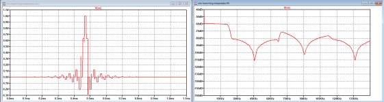
I only corrected a few small things in YOUR model, and see the difference in the images below the original version in red and the corrected one in blue.I don't see what is modified in your asc file.
Impulse response plus FR of yours, versus the same for the corrected one.
It's all in the .asc version in #320.
Hans
.
Attachments
Marcel,
It’s nice to see how inventive they where with restricted amount of rom and ram.
But just one half band filter such as Hayk used restricts flexibilty of the filter choice, doesn’t it?
Hans
True, but Hayk already restricted that when he came up with a requirement he calls sample sacredness. If I understand his requirement well, he wants one of the polyphase decompositions to produce the original sample values, which implies that the impulse response of one of the polyphase decompositions has to consist of a bunch of zeros with a single 1.
I don't see neither any filtering I am doing to be associated with low pass filtering. All I am doing is sinc interpolation to harvest mid sample values and merge to the original. My approach is in time domain, low pass filtering is in frequency domain.
Convolution in the time domain = multiplication in the frequency domain
Convolution with a sinc in the time domain = multiplication with a rectangular function in the frequency domain, also known as ideal low-pass filtering
I did not do any zero stuffing, all I say that it is effectively a smart execution of zero stuffing.I don't see neither any stuffing of 1's instead of zero's as you do, I don't see neither any filtering I am doing to be associated with low pass filtering. All I am doing is sinc interpolation to harvest mid sample values and merge to the original. My approach is in time domain, low pass filtering is in frequency domain.
1) Look at the example below where samples ABCDEFG are coming in.
With zero stuffung they become 0A0B0C0D0E0F0G0
When having a filter with Q0R0S1T0U0V coefficient, output becomes :
Out1=A*Q+0*0+B*R+0*0+C*S+0*1+D*T+0*0+E*U+0*0+F*V or
Out1= A*Q+B*R+C*S+D*T+E*U+F*V
After one shift we get output2 from the filter:
Out2=0*Q+A*0+0*R+B*0+0*S+C*1+0*T+D*0+0*U+E*0+0*V or
Out2 =C
So halve samples can be processed with coefficients QRTUV without zero stuffing and be multiplexed with the original samples.
That's how your algorithm goes, for the full 100% equal to zero stuffing while using a filter twice as long with many zero's and a 1 in the middle.
That's what makes this trick possible because you happen to use a filter with all those alternative zero's and one 1.
Take another filter that does not have all these alternative zero's and you will need two parallel filters instead of one, both still working at Fs followed by the same multiplexing at 2Fs.
2) As a matter of fact, convolution in the time domain is the same as filtering in the frequency domain.
Hans
P.S. I see that Marcel already answered some of it.
Last edited:
probably you posted mine in 320. Poste again please yours. This what I see on post 320.I only corrected a few small things in YOUR model, and see the difference in the images below the original version in red and the corrected one in blue.
Impulse response plus FR of yours, versus the same for the corrected one.
It's all in the .asc version in #320.
Hans
.

I don't understand why you delay the original samples by 15.5 samples and why the clock ck is reversed by delaying 11us. All I see from the FFT the OS to be this.

Are you sure mine was wrong? I make the OS to be first the 16th on the positive, as the sampler acts on the rise, and switch to the midpoint on the negative.
Are you sure mine was wrong? I make the OS to be first the 16th on the positive, as the sampler acts on the rise, and switch to the midpoint on the negative.
- Home
- Source & Line
- Digital Line Level
- Analog Delta-Sigma interpolation DAC