Thanks!! Is this specifically expressed and standardised within the red book system?
sorry kokoriantz for a little ot....
//
sorry kokoriantz for a little ot....
//
Last edited:
There are two sinc functions to distinguish. The first is the brick wall that used as low pass filter for anti-aliasing, described here Sinc filter - Wikipedia
And the second is sinc interpolation following the formula

If the first sinc filter is easy to implement, the interpolator is problematic.

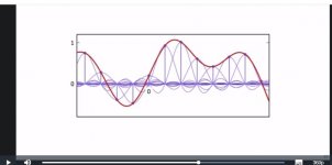
An example of few points is this. Each sampled point has its sinc calculated all added.

3.2.1.c Sinc interpolation - Module 3.1: Interpolation and Sampling | Coursera
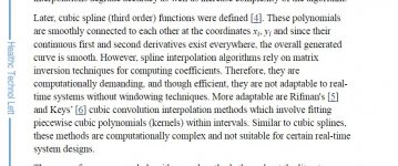
If the sinc interpolator needs many samples, the cubic spline is best whished for four samples only but too difficult to implement digitally.

And the second is sinc interpolation following the formula

If the first sinc filter is easy to implement, the interpolator is problematic.
An example of few points is this. Each sampled point has its sinc calculated all added.

3.2.1.c Sinc interpolation - Module 3.1: Interpolation and Sampling | Coursera
If the sinc interpolator needs many samples, the cubic spline is best whished for four samples only but too difficult to implement digitally.

Attachments
Last edited:
Thanks!! Is this specifically expressed and standardised within the red book system?
sorry kokoriantz for a little ot....
//
No, it's much older than that, see section II of Claude E. Shannon, "Communication in the presence of noise", Proceedings of the IRE, January 1949, http://userweb.eng.gla.ac.uk/charles.ironside/comms4/ShannonClassic.pdf Actually, in an earlier article from 1948, Shannon wrote that it was common knowledge for communications engineers.
There are two sinc functions to distinguish. The first is the brick wall that used as low pass filter for anti-aliasing, described here Sinc filter - Wikipedia
And the second is sinc interpolation following the formula
View attachment 922885
If the first sinc filter is easy to implement, the interpolator is problematic.
One is not more or less problematic than the other: both can only be approximated because of their impulse response that extends infinitely far in both directions. You can approximate them quite well, though.
If the sinc interpolator needs many samples, the cubic spline is best whished for four samples only but too difficult to implement digitally.
I don't know much about cubic splines, but if you can't describe them in terms of a convolution with an impulse response, they are probably non-linear and cause distortion.
I made a typo in my previous posting.
In the example the analog filter has 3 octaves and not 7 to achieve the required attenuation.
Hans
In the example the analog filter has 3 octaves and not 7 to achieve the required attenuation.
Hans
Interpolation is to decrease the harmonics of step character. With cubic spline they are expelled above 3×fs. With interpolating the derivative and passing through an integrator, the harmonics are smashed even without any extra filtering. The FFT of simulation shows clearly.One is not more or less problematic than the other: both can only be approximated because of their impulse response that extends infinitely far in both directions. You can approximate them quite well, though.
I don't know much about cubic splines, but if you can't describe them in terms of a convolution with an impulse response, they are probably non-linear and cause distortion.
For my understanding, what would be the result if you put this signal into your cubic spline interpolator:
..., 0, 0, 0, 0, 0, 1, 0, 0, 0, 0, 0, ...
where ... means that the zeros repeat indefinitely on both sides?
If the 1 were replaced with some constant x0, would the output signal just get x0 times larger?
If so, then would an input signal
..., 0, 0, 0, 0, 0, x0, x1, x2, x3, 0, 0, 0, 0,...
result in the sum of four time-shifted responses as calculated in the first step, scaled by factors x0, x1, x2, x3?
No, it's much older than that, see section II of Claude E. Shannon, "Communication in the presence of noise", Proceedings of the IRE, January 1949, http://userweb.eng.gla.ac.uk/charles.ironside/comms4/ShannonClassic.pdf Actually, in an earlier article from 1948, Shannon wrote that it was common knowledge for communications engineers.
I'm aware that he sample theorem(s) are old - what I ment was if the red book standard has specified symmetrical filters i.e. filter characteristics in the ADC and the DAC that shall match as you describe?
//
I never read the Red Book, but the answer must be no, as early CD players used different types of filters. Most of them were non-oversampling models with analogue minimum-phase filters, but those from Philips used four times oversampling with a linear-phase FIR filter.
In any case, there is no need for the filters to match. If the CD was recorded with some unusual type of anti-aliasing filter, you can still reconstruct its output signal with a linear-phase brick-wall filter - just as long as the signal was band-limited to below the Nyquist frequency before sampling, you can reconstruct that band-limited signal.
In any case, there is no need for the filters to match. If the CD was recorded with some unusual type of anti-aliasing filter, you can still reconstruct its output signal with a linear-phase brick-wall filter - just as long as the signal was band-limited to below the Nyquist frequency before sampling, you can reconstruct that band-limited signal.
What do you think about this
https://www.ti.com/lit/an/sbaa377/s...78685&ref_url=https%3A%2F%2Fwww.google.com%2F
https://www.ti.com/lit/an/sbaa377/s...78685&ref_url=https%3A%2F%2Fwww.google.com%2F
......
In any case, there is no need for the filters to match. If the CD was recorded with some unusual type of anti-aliasing filter, you can still reconstruct its output signal with a linear-phase brick-wall filter - just as long as the signal was band-limited to below the Nyquist frequency before sampling, you can reconstruct that band-limited signal.
Without ringning, as you described above?
What I'm fishing after is if it had been a "better" audio PCM system of it had its filters specified to be symmetrical in the ADC/DAC...
//
With the same amount of ringing as at the output of the anti-aliasing filter, when the reconstruction filter is an ideal low-pass at half the sample rate (which can only be approximated in real life).
You can reduce the ultrasonic ringing at the expense of some treble loss by putting one and (preferably) only one apodizing filter somewhere in the signal chain. Whether this is placed on the recording side or in the DAC doesn't matter.
You can reduce the ultrasonic ringing at the expense of some treble loss by putting one and (preferably) only one apodizing filter somewhere in the signal chain. Whether this is placed on the recording side or in the DAC doesn't matter.
Last edited:
My add/subtract filter is flat to 21khz has no ringing up to 19khz.
The first Philips 14bit + oversampler, you were talking it has linear phase FIR filter, I do remember having seen the pulse response with no ringing, just half cycle negative followed by a positive on the pulse and symmetrical at fall. I will try to find it.
The first Philips 14bit + oversampler, you were talking it has linear phase FIR filter, I do remember having seen the pulse response with no ringing, just half cycle negative followed by a positive on the pulse and symmetrical at fall. I will try to find it.
What should one think about enhancing the sound by suppressing the digital filter?
lampizator_DIY NOS Non Over Sampling modification
lampizator_DIY NOS Non Over Sampling modification
So what about the earlier mentioned harsh sound?
The digital filter mentioned is exactly the upsamling FIR filter I described a few postings ago.
Obviously he did not use an analogue brick wall filter.
Hans
The digital filter mentioned is exactly the upsamling FIR filter I described a few postings ago.
Obviously he did not use an analogue brick wall filter.
Hans
Maybe they just like the treble roll-off caused by the zeroth order hold and the lack of compensation for the roll-off of the analogue filter, maybe the digital filter had an intersample overshoot problem and was hard clipping on peak-sample-normalized recordings.
It's funny to see that everything that was disliked in the 1980's is now in fashion, though; back then linear-phase oversampling CD players were much preferred over non-oversampling CD players with minimum-phase filters. Then again, back then the CDs were not recorded as loud as now, so maybe intersample overshoots were less common.
It's funny to see that everything that was disliked in the 1980's is now in fashion, though; back then linear-phase oversampling CD players were much preferred over non-oversampling CD players with minimum-phase filters. Then again, back then the CDs were not recorded as loud as now, so maybe intersample overshoots were less common.
I am sure have seen the pulse response but I couldn't find it, I found something else here
non oversampling dac

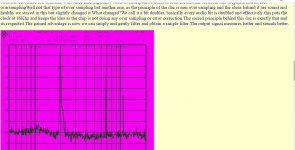
Every audio bit is doubled... What does this means?
non oversampling dac

Every audio bit is doubled... What does this means?
Last edited:
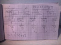
Probably a FIRDAC where two DACs run at 44.1 kHz and their outputs are added, but the details are not clear to me. If they just put 1/44100 s of delay between the DACs, they get a notch at 22050 Hz and a response of -19.9 dB at 20 kHz. Hopefully they did something smarter than that.
It is probably what Accuphase did with 8 Dacs each shifted 1/(8*44.1Khz) and then outputs added as mentioned earlier.
By adding the Dacs you get something of an interpolation with a sinc^2 envelope.
Thus ca -6,3dB at 20Khz.
Hans
By adding the Dacs you get something of an interpolation with a sinc^2 envelope.
Thus ca -6,3dB at 20Khz.
Hans
- Home
- Source & Line
- Digital Line Level
- Analog Delta-Sigma interpolation DAC

