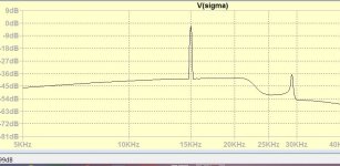
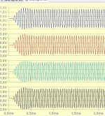
I arrived at a very simple and best result solution. I demodulate the beat by multiplying the delta with the Niquist and I pass it through an RC integrator (to be replaced by true one) and remodulate to obtain back some in phase signal but opposite phase image. The image is smashed to -40db and the amplitude of the signal is increased. It is perfect to 18khz, very good at 19khz and acceptable -20db image for 20khz.


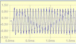
The transients are best what I obtained until now. Note that this circuit doesn't require any filter.
Attachments
Last edited:
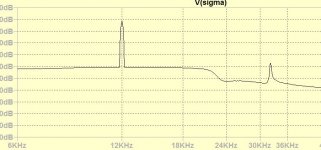
I tried a simpler QPS made of one stage all pass filters. I could harvest pure signal and image from 20khz down to 17khz, but helas , The 20khz transient is always bad. I would like to insist that at frequencies above 8khz, there is no musical instrument that emits continuous waves, all is sharp transients with sharp decaying bursts. If the circuit swallows the sharpness to flatten and lengthen the burst, even the level in continuous is flat the high frequencies sound dark as were the early soft dome tweeters.
Attachments
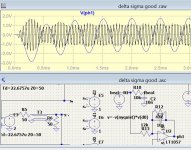
I tried a simpler QPS made of one stage all pass filters. I could harvest pure signal and image from 20khz down to 17khz, but helas , The 20khz transient is always bad. I would like to insist that at frequencies above 8khz, there is no musical instrument that emits continuous waves, all is sharp transients with sharp decaying bursts. If the circuit swallows the sharpness to flatten and lengthen the burst, even the level in continuous is flat the high frequencies sound dark as were the early soft dome tweeters.
Have another look at post #160, https://www.diyaudio.com/forums/dig...a-sigma-interpolation-dac-16.html#post6508803 , and also simulate/measure/calculate what your circuits do at the end of the burst.
Really sharp transients have frequency components above 20 kHz, so when you remove those by whatever means, the transients are not so sharp anymore. If you believe you can hear this, you should use much higher sample rates than 44.1 kHz. If you don't believe you can hear it, then it's a non-issue.
In digital filter world, there are two types that don't have transient pre-echo.

I found in Stereophile Ringing False: Digital Audio's Ubiquitous Filter Page 2 | Stereophile.com
This what I want to achieve by analog way.
What concerns the sound, the starting resonance makes the voice go backwards and loose presence, intelligibility, whereas the ending provokes extra reverberation that many call it as 3D effect.
Minimum-phase filters, especially the steep ones, have a non-linear phase response and their output signal doesn't pass through the sample points that you have declared sacred. Making a minimum-phase filter in an analogue way is easy: just make a filter and don't include any all-pass sections.
You started this thread with some very original linear interpolation and cubic spline interpolation circuits. Those would be interesting to apply as-is to high sample rate recordings, where a bit of roll-off doesn't matter much.
You started this thread with some very original linear interpolation and cubic spline interpolation circuits. Those would be interesting to apply as-is to high sample rate recordings, where a bit of roll-off doesn't matter much.
Last edited:
Above 1/2Nyquist 11khz there is only 3 points and all zero crossings are Nyquist frequency. To determine the lacking points that the sampler missed 1/4*(Fn-f) time of samples are necessary. For this round, I managed by interpolating 5 samples at a time obtained very good results. For now, I can continue my round as I have more details about the requirements. Next, I will design the double PLL, I reconsider the image problem again and again on every round.
Last edited:
I added a high pass to reduce the transient of the filter and it shows there is hope to get the 20khz perfected.


What I like most with this image phase inverter that it auto compensates the sinc level fall some call it droop. despite by delta-sigma I double the sinc droop the level is compensated even to 21khz.

What I like most with this image phase inverter that it auto compensates the sinc level fall some call it droop. despite by delta-sigma I double the sinc droop the level is compensated even to 21khz.
No idea if this post helps, but if I understand it correctly, your requirements are:
1. The output waveform must pass through the sample points
2. It must have little or no pre-ringing
3. The roll-off in the band below Nyquist should not be too large and the suppression of images above Nyquist should not be too small
4. You are looking for an analogue or mixed-signal solution and digital oversampling is not allowed
I will assume that you also want it to be linear time-invariant, so it can be described by an impulse response.
Requirement 1 then implies that there must be points on the impulse response with distances of k Ts, where k is any integer and Ts the sample period, such that one point is 1 and all others are 0. For example, this requirement is met when the main peak of the impulse response is 1 and all points at an integer number of sample periods from that main peak are 0.
Requirement 2 implies that the largest peak of the impulse response must occur close to the beginning of the impulse response.
Requirement 3 is a bit awkward when combined with requirements 1 and 2. The only waveform that passes through the sample points, has no roll-off below Nyquist and no images above Nyquist has infinitely long pre-ringing, so you will have to find some acceptable compromise - something with a bit of roll-off below Nyquist and with finite suppression above Nyquist that meets your requirements 1 and 2.
I was wrong informed that the oversampling resolves the problem of analog post filtering. I never read anywhere linking the beat of frequencies above ½Nyquist and the image frequencies. This why the cubic spine interpolation that forms continuous curves but never exceeding the maximum sampled value is not appropriate to cancel the image frequencies. There is something that is bothering me since 40 years is the sound due to existence of the image frequencies. No human ear can hear these sounds which are over 24khz, Why their existence makes the sound in high frequencies so harsh?
The major problem in reconstructing by interpolation for frequencies above ½Nyquist is to know where is situated the maximum point. As it can not exist any harmonic above this frequency, than it is for sure a sinusoidal wave. If I can know at what ratio between to Nyquist samples it is situated, than by using another type of interpolation I can find from the derivative function where the maximum point could be.
Which other interpolation? First I looked at what is already used, the sinc interpolation. This on line tutorial 3.2.1.c Sinc interpolation - Module 3.1: Interpolation and Sampling | Coursera shows the mechanism, but forgets to explain that it considers to interpolate an oscillatory function as a swing, balançoire, and interpolating gradual increase and decrease of oscillation, at start and the end. The function that I am looking now for eventual interpolation with the derivative's zero crossing is the C spline. This spline is well known to those like me who dealt with naval architecture before computer age where we used flexible wooden battens fixed by lead weights at interpolating points to get a smooth line. I have the formula of this spline but not in Pf form to vary this variable from 0 to 1 and generate the intermediate points. This will be my next challenge.
Last edited:
The high frequencies can cause distortion in amplifiers and possibly in some high frequency speakers/tweeters.
Beyond that, high frequencies can also be harsh because making really good sounding sigma-delta dacs is hard and costly. A dac chip is almost the least of the problems. Lastly, once you know how to make a dac that's good enough, it turns out harsh high frequencies are encoded on many recordings. Maybe the A/D converters they used were to blame, don't know.
Beyond that, high frequencies can also be harsh because making really good sounding sigma-delta dacs is hard and costly. A dac chip is almost the least of the problems. Lastly, once you know how to make a dac that's good enough, it turns out harsh high frequencies are encoded on many recordings. Maybe the A/D converters they used were to blame, don't know.
You don't answer why the presence of ultrasounds make it sound harsh regardless of amplifier or speaker linearity.
Sony CDP-101 Compact Disc Player Page 3 | Stereophile.com
Sony CDP-101 Compact Disc Player Page 3 | Stereophile.com
How do you know they are still linear at very high frequencies, where for amplifiers loop gain falls off? Some tweeters are known suffer audible cone breakup and or other nonlinearities in the presence of ultrasonics. Some opamp circuits in dac boxes don't like too much RF. Ultimately, there have to be reasons for harsh sound, and its pretty clear adult humans don't hear ultrasonic frequencies.
Anyway, a well designed sigma-delta dac running in DSD mode doesn't have to sound harsh.
Anyway, a well designed sigma-delta dac running in DSD mode doesn't have to sound harsh.
Last edited:
I made the following experiment to see if your explanation is correct. I opened two widows on my modest pad, of trueRTA to generate 14khz & 15khz sine waves mixed at 0db both. If the amplifier+ speaker/earphone is generating the IM beat than I must hear the 1khz. Well, I don't hear anything above 14khz, but I would have heard something at 1khz.
Last edited:
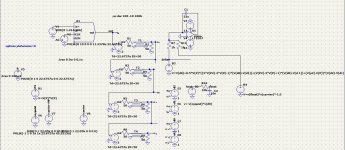
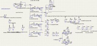
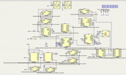
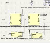
Universal I2C TO 2x PCM Converter

This is the first maquette of I2C to PCM 2 channel converter. It can receive 48khz(44.4) to 192khz data at fix 64 bit/fs and converts to programed to 16-24bit data on 2 parallel channels. It has double PLL to filter the jitter down to 10hz.
How it works?
The fs LRCK is divided by 1 2 or 4 according the bit rate 48,96,192 to bring it to 48khz. Two tone detectors 48khz and 96khz by LM567 decide the division. The 48khz is multiplied by the first PLL by 32 times making it 1.5Mhz. a second PLL multiplies by N the number of DAC's bits 16 to 24. The N is programmed by a down counter and divider by 2. If 20bit DAC is used then the decount is set to 11. It will take (11+1)x2 clocks of division. Now I have a total of 48k×32xN at the output of the second PLL. This frequency is divided back by 32 if the rate is 48khz, by 16 if the rate is 96 and by 8 if the rate is 192 selected by the same multiplexer U6 (drawn twice) and get HCK of fsxN. The LRCK is delayed I clock to form the WSBD signal of PCM.
The data is delayed by 32 bit using a FIFI 4x16 bit. The Data Input ready signal goes low when the input data is shifting for 30ns and remains low when the 16bit are full. a D latch filters the 30ns and gets confirmed by the clock to read the data and pass it to the second raw, making it to shift 16 other bits. The two DATAs now enter the second FIFO to be written at 64bit /fs and be read by N/fs both channels simultaneously and output the RDATA AND LDATA, when the WSBD goes low, it resets the FIFO's counters to restart the next sample.
Attachments
Last edited:
I made the following experiment to see if your explanation is correct. I opened two widows on my modest pad, of trueRTA to generate 14khz & 15khz sine waves mixed at 0db both. If the amplifier+ speaker/earphone is generating the IM beat than I must hear the 1khz. Well, I don't hear anything above 14khz, but I would have heard something at 1khz.
Wrong assumptions. You need to send ultrasonic test signals, possibly up to frequencies of several MHz. I have measured an approximately 2MHz clock square wave at the output of a SOA headphone amplifier driven by an AK4499 dac evaluation board. Now that particular HP amp handled it pretty well. However, the AK4499 evaluation board does have some output filtering so it was not the worst case of a dac without filtering.
The image frequency of 17khz is 27khz, makes a beat of 10khz. How the nonlinearity of amp+tweeter according to your opinion can make it sound harsh?
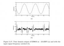
I didn't say its simple IMD of audio-ish frequencies. It involves very high frequencies possibly including up into the megahertz region. The edges of digital pulses have very fast rise times unless they are filtered. To produce such rise times, RF frequencies are involved. In some cases upsampling dacs such as ESS makes, can use a 100MHz clock which produces harmonic frequencies up into the GHz range. For example, a notched out sine wave residual from an opamp in an ESS dac shows random-ish spikes of distortion not perfectly synchronous with the sine wave. Diagram attached below. Doesn't that look like it might sound harsh if it didn't have to pass through further filtering?
Attachments
- Home
- Source & Line
- Digital Line Level
- Analog Delta-Sigma interpolation DAC