Hayk,
What is it that makes you reject upsampling followed by a real good brickwall filter, long enough and accurate enough with a constant GD.
Not many people have tried to improve this brickwall filter that's needed after upsampling to clean mirrors in the spectrum.
So this is really interesting new territory, but you will need a very fast DSP.
If perfectly implemented, it seems by far the superior solution, or is it just the intellectual challenge that causes you to take another route.
When going to 176.4Khz, pre and post ringing is also shifted to 88.2Khz and completely harmless.
Hans


This is the result of oversampling by adding zeros.


The two types of oversampling proves the wrong information that oversampling pushes the image frequencies higher, even though there are lot of documents including from Analog Device that says so.
Should I consider the image treated on post 258 as hoax?
By adding two samples delayed 1fs gives the same image.
Last edited:
I don’t know what exactly you are doing, but didn’t I tell that after adding zero’s the digital spectrum is still the same because you added no information, but only the Sinc has widened after the dac !
So you first need a digital brickwall filter to remove the mirrors.
It seems you added only one zero. So your fir filter should go from 22.05 to 44.1Khz.
After the Dac you will then see the first mirrors from 68.2 to 88.2Khz instead of 24.1 to 44.1Khz.
Hans
So you first need a digital brickwall filter to remove the mirrors.
It seems you added only one zero. So your fir filter should go from 22.05 to 44.1Khz.
After the Dac you will then see the first mirrors from 68.2 to 88.2Khz instead of 24.1 to 44.1Khz.
Hans
I don’t know what exactly you are doing, but didn’t I tell that after adding zero’s the digital spectrum is still the same because you added no information, but only the Sinc has widened after the dac !
So you first need a digital brickwall filter to remove the mirrors.
It seems you added only one zero. So your fir filter should go from 22.05 to 44.1Khz.
After the Dac you will then see the first mirrors from 68.2 to 88.2Khz instead of 24.1 to 44.1Khz.
Hans
Novice question: I've been living with the idea that what the digital filter does is just upsampling thus pushing the images away into the ultrasonic band. So, this looks like a brick wall filter for audio. Is there additional filtering beside that?
When going to 176.4Khz, pre and post ringing is also shifted to 88.2Khz and completely harmless.
I'm not sure what you mean by this, but if you start with a 44.1 kHz sample rate signal and want to suppress the first image, the ringing of the ideal sinc impulse response will be at 22.05 kHz no matter what oversampling factor (> 1) is used.
Magicbus, you have both with digital filter and one without can you describe subjectively according to your listening what difference you hear in high frequency percussion instruments. To my remembrance the first Akai CD player I had, the cymbals sounded as breaking glasses.
It is many documents online describe that by oversampling you chase the image frequencies higher and filtering them becomes simple. This what I show it is 99% wrong because only Sinc interpolation of at least a window of +/-10 samples can do, all others keep the image where it is.I don’t know what exactly you are doing, but didn’t I tell that after adding zero’s the digital spectrum is still the same because you added no information, but only the Sinc has widened after the dac !
So you first need a digital brickwall filter to remove the mirrors.
It seems you added only one zero. So your fir filter should go from 22.05 to 44.1Khz.
After the Dac you will then see the first mirrors from 68.2 to 88.2Khz instead of 24.1 to 44.1Khz.
Hans
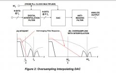
https://www.analog.com/media/cn/training-seminars/tutorials/MT-017.pdf
Attachments
Last edited:
This is PCM1794 in oversampling and NOS mode without any kind of output analog filter. Sigma-Delta might be but it copes with theory. Although I can listen to both, I have to rewire each time so not exactly AB comparison. But I think it's safe to conclude that the treble roll off is audible and also that the NOS makes different -better for me- sound stage. Currently, I'm rebuilding it ...slowly. It will allow to select OS, NOS and some kind of output filter during playback. I'll report back.
Attachments

That's exactly what I said, the spectrum stays the same until you have filtered the images with a brickwall filter.It is many documents online describe that by oversampling you chase the image frequencies higher and filtering them becomes simple. This what I show it is 99% wrong because only Sinc interpolation of at least a window of +/-10 samples can do, all others keep the image where it is.
https://www.analog.com/media/cn/training-seminars/tutorials/MT-017.pdf
Only upsampled AND digital brickwall filtered makes the analog filter simpler.
I start working now on a sim to show you the various steps.
Hans
I agree with you that only the lowpass filter gets rid of the images, but as you see, there are a whole school teaching the interpolator alone shifts the images. To remind that the discussion is about the post 258, how they did it.
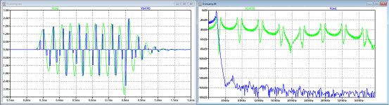
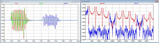
Here is what I promised to do.
I used 50Khz and 200Khz as Fs while that was a bit easier to handle.
I offered a 20Khz sine burst, anti aliased with a 20th order butterworth filter before sampling.
-First image shows signal + spectrum at Fs=50Khz.
-Second image the same but now at 200Khz.
-Third image shows the 50Khz version but now stuffed wit 3 zero's and clocking at 200Khz,
-Fourth image shows time and spectra before and after a 512 points LP brickwall Fir with a passband until 20Khz.
As you can see, Sim is not very much optimised, but good enough to get the message, and as you can see in the fourth image, the mirrors are now around 200K, 400K etc.
A simple analogue LP filter can now remove the the HF content.
Hans
P.S. So the Fir filter is not an upsampling or a reconstruction filter, it is just a LP Brickwall filter.
.
Attachments


Last edited:
I'm not sure what you mean by this, but if you start with a 44.1 kHz sample rate signal and want to suppress the first image, the ringing of the ideal sinc impulse response will be at 22.05 kHz no matter what oversampling factor (> 1) is used.
Yes, you are right, a small slip of the mind.
Hans
Why don't you show clearly the 30khz image with 50khz sampling, and after filling with 3zeros the 50khz image disappear, there it will be convincing.
Sorry, can you please explain in detail what you mean, because 30Khz is above nyquist ???
Why is not convincing in what I have sent, everything I mentioned before is there, zero padding, Fir Filter and D/A.
But my model is working and I can simulate whatever you want.
Hans
Why is not convincing in what I have sent, everything I mentioned before is there, zero padding, Fir Filter and D/A.
But my model is working and I can simulate whatever you want.
Hans
@Hans_Polak & kokoriatz,
could be simply a matter of talking past each other; it happened occasionally in previous discussions of the topic.
Unfortunately the nomenclature isn't strict, so in some lectures the "zero-stuffing" is called "up-sampler" while in audio "upsampling" usually means the whole processing starting with "zero-stuffing" followed by an accordingly choosen low-pass filter.
Zero-stuffing itself provides no low-pass filtering but if the output is a zero-order-hold then of course the overlayed sinc amplitude weighing response kicks in.
Novice question: I've been living with the idea that what the digital filter does is just upsampling thus pushing the images away into the ultrasonic band. So, this looks like a brick wall filter for audio. Is there additional filtering beside that?
As far as you use a multiple of 44.1Khz, it is just brickwall filtering.
But in case you are not using a multiple of 44.1Khz, other steps are to be made to really interpolate in between, or you go to 44,1K*192, followed by a brickwall filter and then decimate to 192K.
Hans
Why don't you show clearly the 30khz image with 50khz sampling, and after filling with 3zeros the 50khz image disappear, there it will be convincing.
Excuse me, but I'm asking you again, what exactly do you want me to do ?
Offering a 30Khz signal without Anti Alias and sample it with 50Khz ??
That means that I get an alias at 20Khz.
That will never disappear after zero stuffing so ?????
Hans
As far as you use a multiple of 44.1Khz, it is just brickwall filtering.
But in case you are not using a multiple of 44.1Khz, other steps are to be made to really interpolate in between, or you go to 44,1K*192, followed by a brickwall filter and then decimate to 192K.
Hans
I'm not at all good in theory but if I may put the question in another way perhaps I could understand better. The graph in post #270 shows oversampling Vs NOS at 44.1kHz. Progressively increasing the sampling rate wouldn't make them look more and more the same?
- Home
- Source & Line
- Digital Line Level
- Analog Delta-Sigma interpolation DAC