Member
Joined 2009
Paid Member
I never did measure it - too lazy.
I calculated it as follows.
The part I used was a TLP190. The specifications are 12uA into a short or 7V open circuit. This is equivalent to a 7V battery with an internal resistance of 7/12u = 580k.
When you put an external speed up resistor in parallel with the output you will cause a voltage drop. You need to ensure you have enough voltage at the output for turning on the FET gates which leads to an external resistor value of order of magnitude 1Meg. I think I used 1.5meg. I was probably overly conservative and a smaller value resistor would have been fine but you do want enough to turn the FETs fully on or they'll have excessive series resistance. With the 1.5M I used the combined internal-external resistance is around 400k. And even then the device was still putting out 7V - the specifications are quite conservative (typical current into a short is more than double the minimum rated value of 12uA I used as a design parameter).
When you want to turn off the FETs you have to discharge the gate capacitance. I assumed a gate capacitance of 4,000pF for each FET. The time constant for discharging this capacitance is RC, or around 400k x 4000pF x 2 (it's x 2 because there are two FETs). If you calculate this out it's only a few milli seconds.
One flaw in this argument is that the TLP190 may not look like a battery when it's turned off and the internal resistance may then be almost an open circuit. In this case the gate discharges only through the external resitor, which in my case is 1.5meg. This is 3 to 4 times slower than I just calculated. But the result is still of order 12mS turn-off time. I think this is fast enough to save a speaker.
Of course, you can always use a regular relay, but I don't think they're going to be much faster. If you do use a regular relate make sure it's a two-pole relay so that the speaker is switched to ground. This is necessary to ensure any dc arcs inside the relay are quenched fast. Unfortunately, the commercial gear I've looked at doesn't bother with this little extra requirement. With a single pole relay I believe the chances are very good that the relay will arc and not protect the speaker.
I know many hate capacitors, but when placed in series with the speaker they can also be used for dc protection - that way you can be really sure. But you need 10,000uF to get down to 20Hz with a 6Ohm load and ideally you want a pair of capacitors back-to-back so it's non-polar which then means you want two 20,000uF capacitors. Then it gets expensive.
Last edited:
Bigun, read the beginning of this thread to see what our project is about.
Well, i have found a photovoltaic able to do 30ns at off operation. Will publish soon simulations results.
Well, i have found a photovoltaic able to do 30ns at off operation. Will publish soon simulations results.
If you calculate this out it's only a few milli seconds.
That's the point.
I am not concerned about the delay. I am concerned about transition time, when the switch turns from low impedance to high impedance.
During this transition time the switch is working in active region and dissipating heat. This loss peak should not exceed the SOA of the MosFet.
If you calculate such error events with high currents and high rails the loss peaks are serious.
But I fully agree that one should not make things to complicated.
For rails up to 50V and realistic loads of about 3R+2mH (4 Ohms woofer with its series choke from the cross over) even a slow loss peak might still be within the SOA of reasonable MosFets.
Let's see the coming simulation from Esperado...
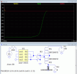
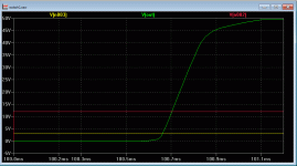
Well, with a simple photovoltaic ASSR-V621 and a mos: IRFP2907 (75V, 200A, 4.5mOhms)That's the point.
I am not concerned about the delay. I am concerned about transition time, when the switch turns from low impedance to high impedance
Off delay is 0.5µs, transition time near instant.
On delay is 1 ms, transition time: 0.55ms
Very satisfied ! No need for more.
Attachments
Last edited:
The integrated turn off circuit of the ASSR-V621 is exactly what I intended to solve with the PNP and diode. Great that they integrated this feature.
Looking like a pretty nice device. ...now I am starting to like this way.
BTW: From your sim for turning off I am reading about 5us delay and about 1us transition time - which still would be perfectly fine and trouble free.
Looking like a pretty nice device. ...now I am starting to like this way.
BTW: From your sim for turning off I am reading about 5us delay and about 1us transition time - which still would be perfectly fine and trouble free.
Yes, sorry for the scale.about 5us delay and about 1us transition time - which still would be perfectly fine and trouble free.
...becoming more and more confident that the photovoltaic couplers with internal or external turn off enhancers are the way to go for most audio amp applications.
Thanks to Esperado and Bigun to trigger me in this direction again.
This simplification is definitely on my agenda when needing again somewhere a MosFet relay.
@Carlos:
Hi !
Yes, I am back - more private chat by PM.
Thanks to Esperado and Bigun to trigger me in this direction again.
This simplification is definitely on my agenda when needing again somewhere a MosFet relay.
@Carlos:
Hi !
Yes, I am back - more private chat by PM.
Now, the voltage of the MOS. What margin would be necessary to afford safe the coil of the speakers+ filters ?
Member
Joined 2009
Paid Member
Esperado, I'm not sure what question you are asking. If you mean there is back emf from the speaker voicoil when the protection kicks-in, this is very true. You need to add catching diodes from the speaker terminal to the power supply rails to divert this back emf away from the amplifier and it's protection circuitry.
By the way, the "assr-v621" looks really nice. I can see that for really high power amplifier this is even better than what I used. Unfortunately, when I search in Digikey online catalogue it's a non-stocked item with large minimum buy quantities.
These look nice: IXYS CPC1909J
http://www.clare.com/home/pdfs.nsf/0/E6D9BA0F358C71CD85256F3500603044/$file/CPC1909.pdf
p.s. I'm not too bothered about the SOA of the FET if it fails Open it's done it's job of saving my speaker.
Last edited:
There is NO question we access to the rails of the power amp in this project.
This protection has the advantage to can work outside of any amp, with no mods, only connected to inputs, outputs and power plugs.
So the only solution i see for the moment is to add 2 zeners in serial, upside down across the Loudpeaker's outputs after the MOS to protect them a cutoff. It looks like it works fine.
See at Mouser for the assr-v621. But there are others. I had chosen this one because found model for it, and a decent data-sheet.
I had tried the same photovoltaic, adding a 10nF cap between sources and gates, no changes in speed.
I will go to IPB025N10N3 G with 100V, 180A, 2.5 mOhms of RDSon.
Last edited:
Member
Joined 2009
Paid Member
I used the IPB200N15N3G as it's around half the price when I last looked. But I'm liking this IXYS part since for $10 it looks well priced and is equivalent to buying two FETs and a photovoltaic.
We would need 8X of them to reach the same RDSon.I used the IPB200N15N3G as it's around half the price when I last looked
I propose all of us, interested in this poject, list the parts they found or will find (accurate active devices) with the datas and source, and if available, link to Spice models.
Once done, we will collect and classify the results for builders can make their choices.
Member
Joined 2009
Paid Member
I think you worry too much about how low Rds has to be - what do you think the resistance of your speaker cable is ?
Besides, I think the IXYS part will suffice quite nicely. It will be easier to use for most constructors too, being through-hole.
Besides, I think the IXYS part will suffice quite nicely. It will be easier to use for most constructors too, being through-hole.
Last edited:
It affect both damping and distortion. I want this protection to be blameless, you know "ultimate" 🙂I think you worry too much about how low Rds has to be
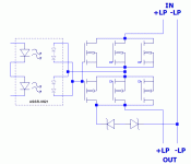
We will try to set the printed circuit to allow 3 sets of traditional MOSFETs (3legs) to be mounted in parallel, reducing their influence by a factor of 10db, as well as one of those (7legs) Infineon ones.
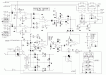
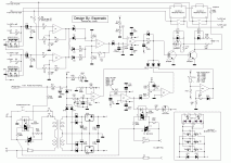
To Coolet, if you update your schematic, i will use-it as the default one in the first post of this topic. Now, i think everything is finisched on it. Changes of values can occur, but i think this can be used to design the printed board.
Attachments
Last edited:
Nice.here it is😉
As 8 serial LEDs were too much for 12V, i have changed the way the static relay is powered. Please refer the original schematic. The value of the 330 ohm resistance had changed, accordingly.
Keep the way you have set the zeners protection, it looks to behave better during power-on.
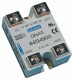
I still do not understand why you have chosen the second version for static relays, they are numerous near all providers. So i will chose the first version, if you agree.
Last edited:
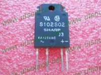
Yes, for the power amp, or this: http://sharp-world.com/products/device/lineup/data/pdf/datasheet/s102s02_e.pdf
They just need to have enough V & A, with phototriac, and 0 crossing detection.
They just need to have enough V & A, with phototriac, and 0 crossing detection.
Last edited:
- Home
- Amplifiers
- Solid State
- An ultimate amp protection circuit ?
