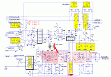
The complete circuit in first message of this thread has been updated.
http://www.esperado.fr/images/stories/protection-totale-definitive.gif
The R19 of soft start can be, or 4xCTNs of 2.5Ohms 5A in serial, (don't use them in parallel), depending of the capacitances and transfo you use, or 1x10 Ohms 50watts wired resistance or any combination.
If you prefer a resistance, it has to be wired outside of the board, and cooled on a raditator.
Different values of resistances for the delay before soft start is short-circuited are given. The following stage, with a delay of 5s add his own delay to the soft start one before music can play.
I hope some help to design the printed board. I think it will be better with discrete components than cms, for easy adaptation. I suggest for the ICs (must be high impedance= fets input) to use 4 in a package, like TL74 for the delays, ond a faster equivalent for the comparator.
Last edited:
I guess this idea about temperature protection maybe can be added or not depending on the builder of the amplifier itself & almost amp already use VBE transistor to control temperature behavior.Hi Esperado,
I see no temperature protection here...
I think we should be add this, quite important one
we can just add one thermal sensor or even two (plus & minus side of output transistor)
How do you think?
Regards
If the amp have enough heat sink it is not necessary but if using small heat sink you must add some few more component here...🙂 (fan/s etc)
And one more thing, an overheat transformer will be a nightmare for all of us
who knows someone borrow our amp and overloaded it 😀
I'm not studying your circuit yet, maybe it is already cover this problem 😎
Best regards
John
Thoughts about your request:I guess this idea about temperature protection maybe can be added or not depending on the builder of the amplifier itself
Temperature sensing is builder dépendant anyway, as a captor has to be glued on the heat sink and accurate temperature triggering of any fan has may vary from one amp to an other.
Anyway, cause i have one opamp free, if we use quads packages. i will add a temp sensing stage to fulfill your request. Will try a choice, using the same components to fire a fan, or fire the protection, as preferred.
is that pronounced like.......... emilio-rations?.......i dont know what it means......but i'm going to start using it!!
I had been learned that, in English, "Elastic" is pronounced "Caoutchouc", and always wonder why English and Americain people don't talk French like everybody else. 🙂emilio-rations?..
"Améliorations" means "Improvements".
Last edited:
Added, using the last unused OPA, a temperature control, based on thermistor.
It can be used or to control a fan, or to fire-up the protection.
I need help to design a printed board.
It can be used or to control a fan, or to fire-up the protection.
I need help to design a printed board.
Last edited:
Hi Esperado
greetings this ultimate amp protector has been on my mind for long is it possible
to get final COMPLETE schematic for it need it for protecting my AB class amps
warm regards
andrew lebon
greetings this ultimate amp protector has been on my mind for long is it possible
to get final COMPLETE schematic for it need it for protecting my AB class amps
warm regards
andrew lebon
I believe it is complete. Just need a printed board design. An i have just to calculate a table of resistance values for temperature protection.
For values of the " R-température" to be tuned according your needs:
http://docs-europe.electrocomponents.com/webdocs/0a9d/0900766b80a9ddbc.pdf
Some values had been added on the schematic.
http://docs-europe.electrocomponents.com/webdocs/0a9d/0900766b80a9ddbc.pdf
Some values had been added on the schematic.
Hello
Hi Esperado
greetings can you please give the values of parts within black box
some parts are very hard to get but i am searching my AB class amp is in
the range of 1.5kw at 85 volts dc+/- will this protector be adequate dont need
temprature protection please can you help out
warm regards
andrew lebon
Attachments
Diodes put of U1/U2 are just any Schottky low drop diodes. All other diodes except rectifiers are any low power silicon diodes.Hi Esperado
greetings can you please give the values of parts within black box
some parts are very hard to get but i am searching my AB class amp is in
the range of 1.5kw at 85 volts dc+/- will this protector be adequate dont need
temprature protection please can you help out
The input solid state static relay can be: G3VM PCB Omron. ( MOS FET Relays G3VM-351B/E | MOS FET Relays | Signal Relays | Relay | Products | OMRON Electronic Components Web). But you need-it only if want to remote the power on of you amp with a 12v signal.
Some other values had been given in this thread.
The operational amplifiers are quads. U need to be as fast as possible, K high impedance (fets) and both no latches at+-12v: Avoid TL074.
No problem for your class AB amp: Chose the static relay and R10 or NTC according your power.
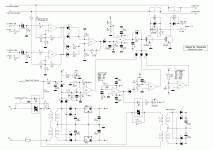
Looks very cool and much simpler ! Congratulations and thanks a lot.schematic redrawn... please double check for error
The only difference is see is the 700E values instead of 750E, near power from preamp. don't think any effect. Value of C? can be 0.1µF.
You have changed the value of adjustable of Speakers levels: perfect. Easier to fine tune.
The 'amp supply' has no reason to be in the schematic, just AC connexions.
Green, yellow and red LEDs are out of the board, too (front of the amp) as we will see them fire during power-on sequence: red when power-on, yellow when end of soft start, green when Loudspeakers connected.
Last edited:
schematic redrawn... please double check for error
Looks like an awful lot of components for a basic task.
I used a PIC micro to detect DC on output and do soft start.
Hello Coolet
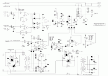
greetings any part no of opto triac used in schematic coolet you are a great proffessional pcb designer any chance for a pcb design if its possible
warm regards
andrew lebon
greetings any part no of opto triac used in schematic coolet you are a great proffessional pcb designer any chance for a pcb design if its possible
warm regards
andrew lebon
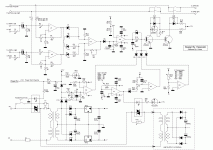
here is the original schematic from the author and modified schematic using moc3041.
Attachments
Last edited:
Oh, it seem the you forgotten the speakers mosfet relays ?here is the original schematic
It optional, but offer some advantages as explained. Whatever people like to use them, or not, it would be nice to have them on the schematic and the future PCB.
[edit]Fine spirits thought the same things in the same time 🙂
Thanks for coming.Looks like an awful lot of components for a basic task.
I used a PIC micro to detect DC on output and do soft start.
I'll have a look at it for K4. No need, i think, for K2: It is just an extra tempo.K2, K4 need hysteresis feedback, and capacitor damping.
Last edited:
- Home
- Amplifiers
- Solid State
- An ultimate amp protection circuit ?


