Just in case anyone missed that important message:
A mains powered SMPS uses a capacitor as the source of DC for the switching supply.
That capacitor is connected to the mains supply. It charges to the mains peak voltage.
That capacitor and the mains fuse MUST have a Soft Start.
The Mains powered SMPS MUST have a Soft Start. The mandatory Soft Start is built into the input of the SMPS
pcb
"If you only need protection, it needs minimal components count.
You are free to design a very little SMD board with just the protection parts. "
Maybe Alexmm would do this for us🙂
"If you only need protection, it needs minimal components count.
You are free to design a very little SMD board with just the protection parts. "
Maybe Alexmm would do this for us🙂
I believe a pure SMD version should be really fine.Maybe Alexmm would do this for us
But Alexmm had worked & suffered so much on his wonderful complete one.
Last edited:
Hello Esperado
greetings post#323 what are the values of R15 C21 and for intial testing
can a mechanical relay be used or both solidstate and mechanical have to be
used together
warm regards
Andrew
greetings post#323 what are the values of R15 C21 and for intial testing
can a mechanical relay be used or both solidstate and mechanical have to be
used together
warm regards
Andrew
What is the gain of your amplifier ? Or, if you prefer, the resistance's values of the feedback network ?what are the values of R15 C21 and for intial testing
The goal is just to attenuate the output of the amp in order to get the exact same level than the input signal, while the P1 &P2 positions are near the middle (500 Ohms). The caps can be neglected in a first time: they are just here to compensate phase turns at 20KHz if you amps is slow.
The level will be: V X (824/(R15+1324)). Where V is your output signal, and R15 in ohms.
You can use any of them or the both together. The solid state relays are faster and more reliable in time. They are less linear than the mechanical relays. All together is overkill and blameless.can a mechanical relay be used or both solidstate and mechanical have to be used together
Last edited:
ultimate protector
Hello Esparado
greetings and thank you for replying its a wonderful project for
my AB class PA amplifier output voltage is 40 volts ac output
peak current 40 amperes now i have most parts only few
resistors which should arrive soon to start this project
warm regards
Andrew
Hello Esparado
greetings and thank you for replying its a wonderful project for
my AB class PA amplifier output voltage is 40 volts ac output
peak current 40 amperes now i have most parts only few
resistors which should arrive soon to start this project
warm regards
Andrew
I need to know the gain of your amp, not its max power.
If you prefer, what is the voltage at outputs for 100 mV RMS in its inputs.
Or, if you can provide a link to its schematic ?
If you prefer, what is the voltage at outputs for 100 mV RMS in its inputs.
Or, if you can provide a link to its schematic ?
single side pcb pl
gentleman pl design single side pcb for this protection circuit,it will very much help full to diy community .
thank you
guru prasad
gentleman pl design single side pcb for this protection circuit,it will very much help full to diy community .
thank you
guru prasad
GURUPPA Rao Alex mm pcb MAESTRO will help us i am also interested in this project
warm regards
sameer
warm regards
sameer
Hello Alexmm
greetings have you tested the ultimate short circuit protector
warm regards
Andrew
greetings have you tested the ultimate short circuit protector
warm regards
Andrew
Hi Andrew,Hello Alexmm
greetings have you tested the ultimate short circuit protector
warm regards
Andrew
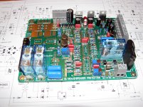
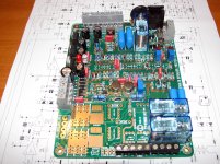
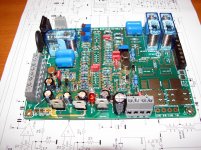
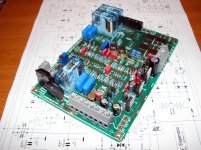
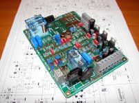
My work it's in progress ,few pic's below. Missing some parts ......🙁
Regards,Alex
Attachments
Hi Alex
greetings your work is proffessional i am one of your fans this project has been on
my mind for a long time hope to make it some day
warm regards
Andrew
greetings your work is proffessional i am one of your fans this project has been on
my mind for a long time hope to make it some day
warm regards
Andrew
Ok. This project to design an ultimate protection board with all the features we can imagine is done.
Time, now, to go in an opposite direction with the same idea: a very little and simplified one.
This protection can work with ordinary relays alone, Low RDS-ON Mosfets alone (we gave two choices for them on the board, that you can chose in between), or the two together, relay + mosfets.
About ajustements, so easy. The two first adjustables have to be tuned to adjust the balance between Output signals and input ones, depending of the gain of your amp. Feed your amp with a 1KHz signal, charged by a resistance or any 6Ohm passive charge. Adjust for each channel the P1 & P2 in order to minimize the signal, watching at the out of U1 & U2. Done.
Now, set the level of your generator at the limit of clipping (just a very little cliping), and adjust P3 & P4 for it is at the limit for the protection to fire on.
Then, play music at the highest level you can afford with your system, and adjust those again (increasing the thereshold) if the protection fires-on.
Time, now, to go in an opposite direction with the same idea: a very little and simplified one.
Was-it not clear that those mosfets were optional ? As well as all the other features, just populating the board according you needs ?I like your protection. If you can simplified it using TL074 and optional ordinary relay (because mosfet with low RDS-ON is hard to find here), I will make the PCB layout.
And please explain how to adjust it, if there are any adjustment need.
This protection can work with ordinary relays alone, Low RDS-ON Mosfets alone (we gave two choices for them on the board, that you can chose in between), or the two together, relay + mosfets.
About ajustements, so easy. The two first adjustables have to be tuned to adjust the balance between Output signals and input ones, depending of the gain of your amp. Feed your amp with a 1KHz signal, charged by a resistance or any 6Ohm passive charge. Adjust for each channel the P1 & P2 in order to minimize the signal, watching at the out of U1 & U2. Done.
Now, set the level of your generator at the limit of clipping (just a very little cliping), and adjust P3 & P4 for it is at the limit for the protection to fire on.
Then, play music at the highest level you can afford with your system, and adjust those again (increasing the thereshold) if the protection fires-on.
Last edited:
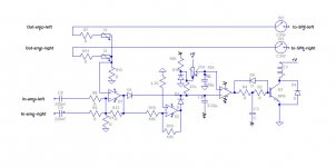
We can imagine something like this (See attached).
The signals from Amplifiers out are mixed together via R7&R11 adjusted to have the exact level of the amplifier inputs via I1 & I3, while amplifiers inputs are mixed via R6 & R5.
U1 compare them, and amplify their differences (If any). D1 fire the protection on positive errors alternances.
U2 invert the error signals allowing D2 to do the same on negative alternances. .
The last OPA allow us to fix a thereshold for the protection to fire-on.
C1 fires-on the protection during power-on sequence, in order to add silence.
C3 +C1 fixe a delay to keep the protection-on for long enough if the error is short, to avoid flip flap trouble if things like little clipping occurs.
We still have a free OPA, using a quad, we will see if we can use-it for soft start, of if we need some additional gain.
Attachments
Last edited:
It is not. Was-it not clear enough ? Just a schematic diagram for the moment and for a start.is this the real schematic
Hello Esperado
greetings its ok when you post circuit with all values i will try it
nothing like a try
warm regards
Andrew
greetings its ok when you post circuit with all values i will try it
nothing like a try
warm regards
Andrew
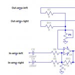
To begin, let's simplify more the input stage. On the previous schematic, two adjustable were set to adjust independently the levels of the two channels.
Well, independently, not exactly, as each variation of the impedance of one channel will affect a little the other. It will be boring to adjust.
I think we can afford 1% of error with no trouble. So, let's use two resistances of 1% of precision and an unique adjustable.
Next step, we will look at the gain of this first stage. and see if we can find a good compromise between bandwidth (phases) and gain.
Attachments
Last edited:
For the gain, i think we can try our protection to fire with any DC > 1.5V. It is low enough to keep safe even the most fragile tweeter. It is <1W on a 4 ohms load.
And to protect any amp between let's say, 10 to 1000W. Seems OK ?
And to protect any amp between let's say, 10 to 1000W. Seems OK ?
Last edited:
- Home
- Amplifiers
- Solid State
- An ultimate amp protection circuit ?