Hello Esperado
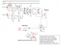
greetings is last schematic final for testing can TLO74 ic be used and
diodes D1 D2 D3 what number should be used and for supply +/- 12v
regulated supply is it ok
warm regards
Andrew
greetings is last schematic final for testing can TLO74 ic be used and
diodes D1 D2 D3 what number should be used and for supply +/- 12v
regulated supply is it ok
warm regards
Andrew
It will work.is last schematic final for testing can TLO74 ic be used and
diodes D1 D2 D3 what number should be used and for supply +/- 12v
regulated supply is it ok
But there is a phase problem if you want to detect accurately very high frequencies oscillations at little levels from your amp. So, if you can find lot faster OPA (with FET inputs). I greatly recommend-it.
Diodes can be any little ordinary commutation ones from your trash can. 0.7V of drop, > 24 V of reverse voltage.
For the mechanical relay, look at the original complete schematic: better to use a separate +V from non regulated PSU to feed-it, to avoid parasitic influence during commutation, and don't forget the protective diode.
+-12V has to be the cleanest as possible, And don't forget 0.1µf decoupling caps right at the OPA(s) +- rails.
Last edited:
Hello Esperado
greetings thank you for replying i have the orignal LT 1364 ics for now
i will use TLO74 for the +/- 12v regulated supply i will use LM317 337T
low noise supply which is ready thanks for reminding me of the .1uf
decoupling caps and can you please explain the testing steps
warm regards
Andrew
greetings thank you for replying i have the orignal LT 1364 ics for now
i will use TLO74 for the +/- 12v regulated supply i will use LM317 337T
low noise supply which is ready thanks for reminding me of the .1uf
decoupling caps and can you please explain the testing steps
warm regards
Andrew
Charge your amp with a 100Hz sinus signal at full power, a little under clipping with a resistive load that can afford the power.can you please explain the testing steps
Tune precisely the 10 turn 1K adjustable to minimize the signal at the out of the first OPA looking with an oscilloscope. Peak of the error signal is what matters.
Done.
Tune the second adjustable at the limit to avoid any outbreak of the protection. Decreasing its serial value increase the gain /sensitivity. Now, you can just clip your amp to see if the protection fires.
Now, play music with your enclosures , and, if necessary, decrease the gain of the second adjustable if the protection fires with loud kick drums.
Hello
Hello Esperado
greetings just want to ask you diode mur160 is ok for protection
just trying to make a rough pcb once protection is working will
try with faster OPA ics is for a pa amp this protection amp is
robust 1 ohms load it can play first time i make pcb so if you
feel its not good for testing let me know pcb still unfinished
warm regards
Andrew
Attachments
No problem, but you could use 1N4448 as well.Hello Esperado
just want to ask you diode mur160 is ok for protection
Nice one.just trying to make a rough pcb once protection is working will
try with faster OPA ics
I think so.is for a pa amp this protection amp is
robust
???1 ohms load
Never tried such a low impedance !!!
(I had no time yet to verify your board. Anyway, try to use the same Relay in the BOM of the big board, 2 paralleled contacts. And if this protection is supposed to work on stereo amp, use two of them with two transitors.
Too, no need of a 10 turn adjustable for the 10K.)
Would there be interest in a small PCB with the original, tested, high accuracy sense/channel ckt, plus the soft start comparator ckt?
1--- LM339 quad comparator $0.50.
1--- TL084C quad JFET opamp for control functions $0.50.
-----Option: OPA4134 quad JFET opamp $5.00.
1--- LM339 quad comparator $0.50.
1--- TL084C quad JFET opamp for control functions $0.50.
-----Option: OPA4134 quad JFET opamp $5.00.
Attachments
Hello
Hello Esperado
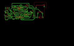
greetings if possible please can you check pcb and component
layout if possible as its the first time i have designed a pcb
if everything works ok will try with faster opa ics 12 volt +/-
regulated supply is on a another pcb its just a test run
warm regards
Andrew
Hello Esperado
greetings if possible please can you check pcb and component
layout if possible as its the first time i have designed a pcb
if everything works ok will try with faster opa ics 12 volt +/-
regulated supply is on a another pcb its just a test run
warm regards
Andrew
Attachments
Do-you feel-it necessary ? The big board exists, and you can populate what you want in it. It was done in this spirit.Would there be interest in a small PCB with the original, tested, high accuracy sense/channel ckt, plus the soft start comparator ckt?
1--- LM339 quad comparator $0.50.
1--- TL084C quad JFET opamp for control functions $0.50.
-----Option: OPA4134 quad JFET opamp $5.00.
Give me a little time, i'll do-it. Thanks for your interest. I insist on the relay: please, chose the one in the BOM of the big board.can you check pcb and component
layout
Hello Esperado
greetings thank you for taking interest in my pcb please can you give relay
number for testing on pcb is a 12 volt 30 ampere relay next step is a mosfet
relay for faster switching and high amperes as i have tested 3 short circuit
protections with very good results so please tell me what relay to use yes
i know mechanical relays are not good
warm regards
Andrew
Do-you feel-it necessary ?
A speaker's resistance can vary from 120-ohms at resonance down to 3 ohms in the pass band. A 200W woofer on one amp channel can have 4mH of phase-shift inductance, while a 20W tweeter on the other amp channel can have 0.004mH of inductance. A bi-amp crossover circuit will dramatically shift phase and power between channels. Large variations in resistance and power, impedance and phase between the two amp channels. If you sum them together at one opamp input, it looks like a very coarse detection-level is necessary to avoid false triggers, or dead speakers from the requirement to save a 20W tweeter on one channel, with a 200W woofer booming on the other channel. The original, tested, high accuracy, sense/channel ckt should allow more accurate triggers, .....with about the same cost and PCB area.
For just basic error detection, the cost and area of the power supply and relays dominate. The original sense/channel uses just 1_quadAmp + 1_quadCompare. I think more customers would purchase this design.
Last edited:
There is no "customers" as it is a "non commercial" design for Diyers.For just basic error detection, the cost and area of the power supply and relays dominate. The original sense/channel uses just 1_quadAmp + 1_quadCompare. I think more customers would purchase this design.
Remember that we measure is the output of the amp, with very low internal impedance. And, if any phase problems, remember it is for stereo. Means same phase angle for the two amps.
You prefer the big one ? Perfect, go for it.
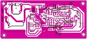
andrewlebon , Your board looks OK. Found only 1 little error of marking.
Cap 330µF marked 47µF.
About Relay, the ones in the BOM is:
2T 16/20/30A
12V < 250mA Finder 62(65) .32-0300
You'll need two of them for two channels, in order to keep the 2 contacts // for each one.
And two transitors (one for each).
Cap 330µF marked 47µF.
About Relay, the ones in the BOM is:
2T 16/20/30A
12V < 250mA Finder 62(65) .32-0300
You'll need two of them for two channels, in order to keep the 2 contacts // for each one.
And two transitors (one for each).
Last edited:
Hello Esperado
greetings 47uf marked on pcb will be 330uf i will look for the finder relay
will protection work for mono amplifier or it will work ONLY on stereo amp
warm regards
Andrew
greetings 47uf marked on pcb will be 330uf i will look for the finder relay
will protection work for mono amplifier or it will work ONLY on stereo amp
warm regards
Andrew
And, if any phase problems, remember it is for stereo. Means same phase angle for the two amps.
ONE Bi-Amp is put behind each speaker, with one channel going to the high power woofer w/Xover, and the second channel going to the low power Mid+Tweet w/Xover. It is common for channel_1 to pump 200W+ to the ported 4mH woofer with a Xover circuit creating the 180-360 degree phase shift, while channel_2 drives a 40W sealed 0.5mH MT with a 90 degree phase shift crossover circuit.
A single summation opamp would need to be set coarse enough to allow large woofer transients, and also sensitve enough to avoid high frequency tweeter kill.
If you design a board, why not do-it for stereo or remove the double inputs ?Hello Esperado
will protection work for mono amplifier or it will work ONLY on stereo amp
LineSource, I don't understand what you want. Again, chose your poison.ONE Bi-Amp is put behind each speaker
If you use active speakers, you don't need a protection against short circuit. For the worse case, you can have one against amp faillure: DC in output. Those two protections are overkill on this point at minimum of sensitivity : no phase problems.
If you use bi amp, i suppose you are using a big streo amp for basses and a little one for trebles, two stereo protections, one in each stereo amp. And again, phase is the one of the amp, not the speakers, I hope for you that your amps are not turning their phases at low frequencies, depending of the charge. They can change their phases at HF depending of their bandwidth and stability margins. And even if you add the two (basses and trebbles) on the same protection, you can reject basses as much as you want (no phase problems), and concentrate on the treebles
We are not going to argue endlessly on this point.
Last edited:
Christophe,
I'd love to see the simplified design of a small protection circuit for just what you mentioned an internal self powered amp where you would never get a short and the load is always the same load. Something small that only does what is needed in this type of situation. I do understand how much more difficult this is when you have no clue what speaker the amp will be connected to, that is the worst case, mine is the best case I would think.
I'd love to see the simplified design of a small protection circuit for just what you mentioned an internal self powered amp where you would never get a short and the load is always the same load. Something small that only does what is needed in this type of situation. I do understand how much more difficult this is when you have no clue what speaker the amp will be connected to, that is the worst case, mine is the best case I would think.
- Home
- Amplifiers
- Solid State
- An ultimate amp protection circuit ?