Oh, i realize i have not the slighest idea of the RDS & RDS changes of those MOS in reverse.you get a net 4 milliohms for the two in series.
Clever idea, as habit.It might be interesting if it were a problem in some other context to actively vary the gate-source voltages to stabilize the resistance. But certainly I'm not suggesting that it is needed here..
As i was asked questions about the complexity of this circuit, it think i better go back in my shelter 🙂
May-be that's explain why i was not sure if i can hear any added distortion. Anyway, i think that, if any, it can be cured by some Bybee Quantum Purifiers 🙂EDIT: And that is an astonishingly flat Ron at 10V Vgs.
I had spend some hours to find those devices, may-be the reason why i tortured sir Alex to have them inboard..
Last edited:
I would expect them to be pretty symmetrical. And back-to-back matched asymmetry would be cancelled, except for asymmetrical material. No, I don't think there is much to worry about thereOh, i realize i have not the slighest idea of the RDS & RDS changes of those MOS in reverse.
So, my doctor was right, pretending my insomnia were only due to coffee abuse and my psychoanalyst because i was jealous of the talent of Sir Alex.No, I don't think there is much to worry about there
.
Member
Joined 2009
Paid Member
I would like to add that nothing seems to stops the DIYers to set the mosfets directly inside theirr amp, right at the side of the power transistors. ...
I was wondering when this would turn up. I simulated this last year.
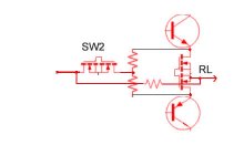
What I was looking at was having the FETs on resistance provide the emitter degeneration for the output devices.
There's more - I was considering if I could modulate the on resistance of the FETs so that the emitter degeneration of the power devices was dynamic. Think about compression of the signal at high current. Think about manipulating the cross-over in a Class B pair.
I never did take the simulations to a conclusion though - but I think it is a very interesting area to explore. 😉
I was wondering when this would turn up. I simulated this last year.
What I was looking at was having the FETs on resistance provide the emitter degeneration for the output devices.
There's more - I was considering if I could modulate the on resistance of the FETs so that the emitter degeneration of the power devices was dynamic. Think about compression of the signal at high current. Think about manipulating the cross-over in a Class B pair.
I never did take the simulations to a conclusion though - but I think it is a very interesting area to explore. 😉
Along somewhat similar lines one could use them to introduce a small variable loss with the effect of removing residual distortions from the amplifier. I considered this as a technique in particular for switchmode amps, in analogy to but in contrast with active "class A" stages embedded in switchmode amps, like Devialet and various other approaches.
The devices could be in parallel rather than in series, and in the "ground" leg, i.e. the speaker return conductor, which would make the manipulation of the gate voltages somewhat easier. If the circuit breaker function were to be included then they would have to be in series.
The problem, them, will be power dissipation of the protection mosfet, when we want it to deal with as less power we can, for safety.IWhat I was looking at was having the FETs on resistance provide the emitter degeneration for the output devices.
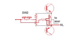
Before to look at this question, we have to solve the feedback problem. it seems impossible to keep a constant gain in the amp, during commutation and normal use, at power on.
The first idea i had was as attached, using an other low power switch to bring back FB when main switch is off. But the time constants of the switches, different between models and on/off operation make the thing impossible.
So, we need additional circuitry to disable detection during switching time.
i gave-it up.
Attachments
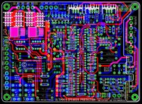
Nice idea to had added an optional mechanical relay for remote power on.rev 1.9 born today late in night 🙂
More and more beautiful., Alex !
Definitively more harmonious on some details, like the AC remote plugs position and less acrobatic here or here 🙂
I know it is boring to repeat, but your work is amazing, and the time you offered to all of us is a priceless gift.
Just, at first sight, i'm afraid by the little tracks between Loudspeakers lines of solid state mos relays and the mechanical ones. If some one think it is enough and use them in serial instead of big diameter cables, it is risky in case of short circuit on the speaker lines and will introduce unwanted serial resistance ? I know that the protection will fire-up fast, but, who knows ?
Last edited:
Nice idea to had added an optional mechanical relay for remote power on.
Nice idea, but better do not use this option.
Or redesign the PCB with proper distances for mains voltage and double check also the suitability of the isolation of the chosen relay.
Ensure double/reinforced isolation.
EN60065, Chapter 13.4: Creepages, Table 11
==> Design creepages of at least 5mm
(Creepage = shortest path along surfaces)
EN60065, Chapter 13.3: Clearances, Table 8 & 9
==> Design clearances of at least 4.4mm
(Clearance = shortest distance through the air)
EN60065, Chapter 8.8: (Simplified with my own words and not at all complete...)
In case of single layer isolations ensure at least 0.4mm material thickness and withstand a high pot test of 4kV.
If thinner than 0.4mm then ensure at least 3 layers, whereof already two layers withstand a high pot test of 4kV.
P.S.
Sorry that I am coming up with this so late.
Did not track this great thread for a long time.
Disclaimer:
I am not a safety expert, but interpreting the EN60065 according my best engineering knowledge.
EDIT:
The concerned isolation above is the isolation between mains and the low voltage signal area.
Last edited:
Thanks for your contribution. I'm sure you're right on an industrial point of view. Need to be confirmed by an international expert in safety rules.The concerned isolation above is the isolation between mains and the low voltage signal area.
Notice that the AC parts in the board are protected with a ground track from the rest of the circuit. And have to be isolated with an external isolating protection, to take fingers away, for sure. Can be done with some plastic sheet.
It would be definitely great to get the corresponding info from an US guy regarding UL/ANSI.Need to be confirmed by an international expert in safety rules.
For CCC in China we can expect very close similarities to European standards.
This GND track is not in place at the relay itself.Notice that the AC parts in the board are protected with a ground track from the rest of the circuit.
Furtheron this method also is more complicated. It does not need just some GND, it must be a valid PE (Protective Earth), which provides low impedances and high current capabilities. And then you still have to provide basic isolation vs the hot tracks. Demanded creepages then would be 2.5mm.
In any case I do not recommend to expect that people have proper PE in place. Better design for double/reinforced isoaltion, this will also allow to use the board in a stereo set of protection class 2.
Sorry to come in so late in the game, just re-discovered this thread.
I did go back to look at the schematic, very ingeneous!
The way I understand it, it compares Vin with the feedback signal, which should be the same. If, not, there's trouble and the protection is activated.
My question is, how does it handle clipping? Then the feedback signal will be much lower than Vin, but you don't want to activate the protection (I think). How is that taken care of in this system?
Jan
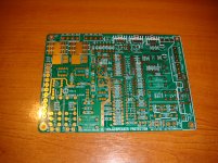
Mail man has delivered a gift from a friend
Hello Alex
greetings hows progress on the ultimate protector nice pcbs
warm regards
Andrew
Hello Alex
greetings hows progress on the ultimate protector nice pcbs
warm regards
Andrew
Not exactly: It compare the input signal with the *output* signal attenuated by a factor equal to the gain of the amp . The same level, indeed than the feedback signal.The way I understand it, it compares Vin with the feedback signal, which should be the same. If, not, there's trouble and the protection is activated.
One of the interest is this protection is universal, can be set outside of any amp with no modification of and in the amp itself.
Connect the preamp lines to the protection inputs, connect the line outputs of the protection box to the amp's inputs, connect little speaker lines from the amp to the protection box, connect the speaker's output on the protection box to your enclosures.
Adjust the attenuation once, to fit your amp gain, and your sensitivity to avoid unwanted activation, done.
Both the amp and the speakers are protected.
Yes, we want to activate the protection when the amp is clipping: because a HIFI amp is not supposed to do this and clipping can be dangerous for some tweeters.My question is, how does it handle clipping? Then the feedback signal will be much lower than Vin, but you don't want to activate the protection (I think). How is that taken care of in this system ?
As we can adjust the sensitivity, we can allow more or less clipping (and TIM) according to our needs.
I used such a protection in my big PA company with no trouble during huge rock'n'roll shows;-) It saved a lot of gears.
I have one in my own home amp from decades. Demonstrated hundreds of short circuits on the speaker's lines. Still well and alive.
nb: Too all my friends here, I have decided to leave this forum, but i will stay on this thread to help builders. You can join-me, too, on my web site, by mail, or PM if you need help.
Last edited:
Please, do not be scared off by the apparent complexity of the schematic.
It is a version with all the options we can imagine. Soft start, silent stop, remote, temp monitoring, multi speed fans command, temperature protection and protection for both speakers and amplifier (including DC from the source).
If you only need protection, it needs minimal components count.
You are free to design a very little SMD board with just the protection parts.
Note that the protection alone is so fast that it will ensure silent start and stop by itself. Any noise or DC during the power on or power off operation of the amp will fire the protection, disconnect your speakers and ensure total silence.
Christophe,
Could you show the simplified schematic of what you just described? Knowing that it will protect the speakers and amp and give a soft start type function and turn off makes that sound very useful without all the other functions.
Could you show the simplified schematic of what you just described? Knowing that it will protect the speakers and amp and give a soft start type function and turn off makes that sound very useful without all the other functions.
You have a nice tool on my web site (see my signature) for this. Click on "Clear all" then "Protection alone".Christophe,
Could you show the simplified schematic of what you just described?
Two 14 pins IC packages, two litle transistors, two power mosfets relays and/or mechanical relays, two little static relays.
And the few diodes, résistances and little caps around.
You can explore all the other options as well the same way.
Nobody noticed this amusing feature ?
Last edited:
The soft start is useful to avoid huge current flows when you use big Linear Psu with a lot of big caps. And ensure long life to them and your home fuses ;-).
No need if you use good SMPS (that i recommand for audio), as they include their own soft start function.
No need if you use good SMPS (that i recommand for audio), as they include their own soft start function.
- Home
- Amplifiers
- Solid State
- An ultimate amp protection circuit ?