Just one word: fantastic.
I think you got-it !!!!! All problems solved, routing done 😀😀😀😀😀 in a brilliant way.
Once more, Sir Alex had challenged his reputation.😎
Just i feel confused by all the work you had done for us.
Having-you on our side is like to have both Steve Gadd and Abe Laboriel on your back, while you plug in your guitar 🙂

Member
Joined 2009
Paid Member
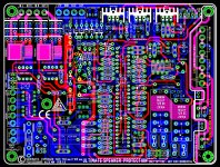
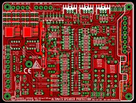
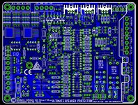
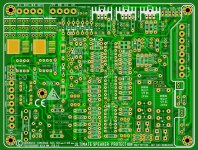
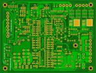
Wow, that's a stunning pcb design. Just printing out those layout plots in colour would make some artwork for the wall !
Holeee cow.
This should be a standalone ? Not an on board protect which is in the amp right ? cos it is likely to be more crazy than the amp. Like my L20 amp has like 18-20 components. This has 10X as many.
Cool.
Srinath.
This should be a standalone ? Not an on board protect which is in the amp right ? cos it is likely to be more crazy than the amp. Like my L20 amp has like 18-20 components. This has 10X as many.
Cool.
Srinath.
No problem at all , so rev 1.8 ready like you ask ......😀
Regards ,
Alex
Beautiful layout work.
This circuit offers all what you need in an amplifier around the amp itself for safe and luxurious use. Can be stand alone, outside of the amp, and work with any existing one, and offer all the feature described. You can populate-it with few parts if you need only protection. Not everiboy needs multi-speed fan control, as an example.Holeee cow.
This should be a standalone ? Not an on board protect which is in the amp right ? cos it is likely to be more crazy than the amp. Like my L20 amp has like 18-20 components. This has 10X as many.
But you can use-it as well inside your next DIY amplifier, concentrate on the amp itself, and let this circuit takes care of soft start, protection etc...
It can seem indeed overkill, like airbags in a car... before the accident.
Class D questions
My compliments , very nice work !
Have a couple of questions regarding using this protection on a class D amp .
Will the protection trigger on the carrier residue on the output of the class D amp ( it's not supposed to be on the input 🙂)
When using both mechanical relays and Mosfet relays combined isn't there still a possibility of welding the mechanical relay contacts in case of a total DC failure and so frying the speaker ?
Last question , I can't find VR2 on the PCB , any reason ?
Thanks and cheers , Rens
I'am afraid yes 🙂Have a couple of questions regarding using this protection on a class D amp .
Will the protection trigger on the carrier residue on the output of the class D amp ( it's not supposed to be on the input 🙂)
We'll have to try if we can make the thing working with a low pass or notch filter to remove as much switching frequency as possible.
By habit, this kind of problem occurs during contact on (this is be done here by the Mosfets), but, you see the thing well: if you use both relays together, the mechanical relay will have to cut the DC, as it is slower. I believe the main risk, by habit, is a deterioration of contact quality with repeated sparks on normal use during power-off. It will not happens here, as the input signal to the amplifier is cut first before the mechanical relay opens, so, this one will have no current to cut, daily.When using both mechanical relays and Mosfet relays combined isn't there still a possibility of welding the mechanical relay contacts in case of a total DC failure and so frying the speaker ?
Oh, you had afraid-me a second 🙂Last question , I can't find VR2 on the PCB , any reason ?
Last edited:
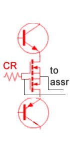
I would like to add that nothing seems to stops the DIYers to set the mosfets directly inside theirr amp, right at the side of the power transistors. With the benefit that they will be included in the feedback loop, reducing further the (very) little distortion due to the Mosfet non linearities with currents. No more reason, for ghosts hunters, to think about mechanical relays. Well, if your amp is able to suffer open loop operation with no charge, that i doubt 🙂
Attachments
Last edited:
ESP,
the solid state relay can be fitted in the Return from the Speaker.
Will your PCB allow this?
the solid state relay can be fitted in the Return from the Speaker.
Will your PCB allow this?
No. What the benefit ? As the relays can be set anywhere in the speaker's loop, thanks to the opto-couplers, why not let them cutting the output ?ESP,
the solid state relay can be fitted in the Return from the Speaker.
Will your PCB allow this?
Last edited:
Please, give a link, or more explanations: i don't see the point: we are dealing with currents, and they are the same everywhere in the speakers+ amp loop.
Christophe, sorry if I missed it as I came to this thread late and may not have reviewed all the posts, but have you evaluated the maximum distortion that might be contributed by the DMOS switches? Note that besides the intrinsic variation of resistance with current there are also self-heating effects that may cause that resistance to change, possibly with time constants in the audio range depending on the devices.
Hi, bcarso, nice to see you here.
I'm terrified to enter in this subject, highly controversial, considering those audiophiles highly trained and armed, prowling all around and able to hear the difference between 10cm of silver cable and coper one in a preamplifier.
I tried to measure distortion change, but , with my old LEA, it was under the measurement threshold.
I'm not sure to hear changes, when i short circuit my mosfets, see what i mean ;-) so i will not mount the mechanical relay witch was just added in order to keep some dignity in the face of this kind of question 🙂
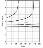
Well, with the typical 2 mOhms of RDS for IPB025N10N3, flat from 0 to 240 Amps with 10V GS, comparing to the 6 ohm speaker, go figure !
And, about thermal effects, in normal operation (10 Watts ?) and 6 ohm speaker, dissipation in the MOS will be: 0.003Watts, i worry more about my moving coils temperature changes 🙂
Oh, excuse-me, i think i have to leave for a while, somebody is calling-me in my anti atomic shelter ;-)
Attrached RDSon of the IPB, (VGS is 8V from the opto-driver)
I'm terrified to enter in this subject, highly controversial, considering those audiophiles highly trained and armed, prowling all around and able to hear the difference between 10cm of silver cable and coper one in a preamplifier.
I tried to measure distortion change, but , with my old LEA, it was under the measurement threshold.
I'm not sure to hear changes, when i short circuit my mosfets, see what i mean ;-) so i will not mount the mechanical relay witch was just added in order to keep some dignity in the face of this kind of question 🙂
Well, with the typical 2 mOhms of RDS for IPB025N10N3, flat from 0 to 240 Amps with 10V GS, comparing to the 6 ohm speaker, go figure !
And, about thermal effects, in normal operation (10 Watts ?) and 6 ohm speaker, dissipation in the MOS will be: 0.003Watts, i worry more about my moving coils temperature changes 🙂
Oh, excuse-me, i think i have to leave for a while, somebody is calling-me in my anti atomic shelter ;-)
Attrached RDSon of the IPB, (VGS is 8V from the opto-driver)
Attachments
Last edited:
OK so those really are very large FETs, and you get a net 4 milliohms for the two in series. If that changes as a function of current and temperature even 10 percent that couldn't be a lot compared to a nominal 6 ohms.Hi, bcarso, nice to see you here.
I'm terrified to enter in this subject, highly controversial, considering those audiophiles highly trained and armed, prowling all around and able to hear the difference between 10cm of silver cable and coper one in a preamplifier.
I tried to measure distortion change, but , with my old LEA, it was under the measurement threshold.
I'm not sure to hear changes, when i short circuit my mosfets, see what i mean ;-) so i will not mount the mechanical relay witch was just added in order to keep some dignity in the face of this kind of question 🙂
Well, with the typical 2 mOhms of RDS for IPB025N10N3, flat from 0 to 240 Amps with 10V GS, comparing to the 6 ohm speaker, go figure !
And, about thermal effects, in normal operation (10 Watts ?) and 6 ohm speaker, dissipation in the MOS will be: 0.003Watts, i worry more about my moving coils temperature changes 🙂
Oh, excuse-me, i think i have to leave for a while, somebody is calling-me in my anti atomic shelter ;-)
It might be interesting if it were a problem in some other context to actively vary the gate-source voltages to stabilize the resistance. But certainly I'm not suggesting that it is needed here.
EDIT: And that is an astonishingly flat Ron at 10V Vgs.
Last edited:
- Home
- Amplifiers
- Solid State
- An ultimate amp protection circuit ?