Another option for an online viewer is here:
Reference Gerber Viewer, by the developer of the Gerber Format
According to that website, Ucamco is the developer of the Gerber Format.
Reference Gerber Viewer, by the developer of the Gerber Format
According to that website, Ucamco is the developer of the Gerber Format.
Thanks to everybody who answered . I have managed to look at them. Looks quite good that board I will take my time to study it now.
Cheers everybody
Cheers everybody
Finally completed my build of this today.
I used the old chipamp.com power supplies, the transformers are +/- 18V 160VA (they were cheaper than the 120VA from the same supplier).
The sound is excellent, really happy with it, and it is extremely quiet, bearing in mind I am 52 years old with some tinnitus.
I have built it for a friend and it will be off to them this week, but I intend to have it playing until then.
I think the only thing I would add is that if you intend to get boards made, edit the gerbers to include text/symbols for the input and output.
My thanks to 00940 and contributors for designing this and making it available, it is much appreciated.
Attachments
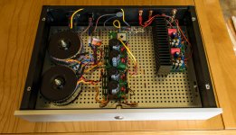
It's a very clean build, nice. Thanks for the kind words too.
Just one detail if I may. Aren't you afraid of the edges of the metal holes biting into the insulation of the live wire ?
Just one detail if I may. Aren't you afraid of the edges of the metal holes biting into the insulation of the live wire ?
You are quite right. I was very careful threading the wire through but didn't account for problems later on. Safety should be paramount, thanks for bringing this to my attention, I will rectify it asap.
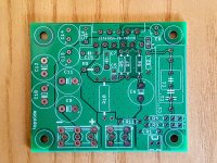
I have decided to get 20 from JLCPCB they have been delivered for a total of 15 euros shipping included so now I will play around with this and see what I can get done. The pcbs seem to be good well done quality. A big cheers and thanks to everyone who contributed to develop them. It may take some time but I will report back on this .
Thanks Michael
Thanks Michael
Thanks to 00940 for this clean and userfriendly design. Thumbs up ! Also many thanks to Neil being so kind to share the PCBs.
Which Caps do you use where ? I can buy all kinds of Wima caps and Nichicons here. Which ones make sense on what position ? They are priced very simmilar, so i would like to go the best possible route... Did someone try different caps ?
Same question for the resistors. Better use non magnetical types at 0.1% or which would be best ?
Finally completed my build of this today.
I used the old chipamp.com power supplies, the transformers are +/- 18V 160VA (they were cheaper than the 120VA from the same supplier).
The sound is excellent, really happy with it, and it is extremely quiet, bearing in mind I am 52 years old with some tinnitus.
I have built it for a friend and it will be off to them this week, but I intend to have it playing until then.
I think the only thing I would add is that if you intend to get boards made, edit the gerbers to include text/symbols for the input and output.
My thanks to 00940 and contributors for designing this and making it available, it is much appreciated.
Hi Neal,
you do not use any DC protection ? Just curious about it... I dont have any protection too, but i am a bit afraid if it would not blow my speakers.
Do you think i can try without ?
I tested it with old speakers, then tested again with old speakers once I had assembled it into the chassis. Then I used it for a week on old speakers before moving on to the newer ones.
I suppose a protection circuit would be prudent though.
I suppose a protection circuit would be prudent though.
My Guardian-86 and Guardian-686 would be good candidates for such a protection circuit. The -686 is the stereo version.
Tom
Tom
I've posted Gerber files for the PSU (#63) and DC protect (#121). They're not as complete as Tom's offerings but they do the basics right. That's what I used for my amp.
As the DC protect has been slightly improved compared to what I got, I don't have available pcb.
@linuxgeek: I wouldn't worry too much about parts, it's meant to be a simple amp. Use good quality brands and you'll be fine. The most critical component is the feedback resistor, which must be metal film.
Hi 00940, like this Dc protect, i would like to use it in my next project, do you have an example of D5 for 35V rail ?- D5 is a big TVS. Its working voltage must be a bit higher than your PS rails.
Thanks
I've been keeping an eye on this thread for a while since i've been planning a small modestly-watted amp for a summer house and this design seems perfect for the task. I've been vaccillating between some of the TPA325x chips and a chipamp, but i've already built a few of the class D offerings and would like to try something different. But i have a few questions for the collective DIYaudio wisdom.
First intendended use: The speakers are a pair of Alpair 10.3 bass reflex standmounts and the room is a bit less than 25 Sqm. I have had these hooked to my BA3FE/Firstwatt F6 combo for a while and that has loads of power (rarely more than halfways to full volume), so i know the LM3886 is probably even overkill, but i'm curious to hear how it sounds. I generally don't listen loud, and my better half is a musician and pretty sensitive to loud music when off duty 😉
I intend to try and use parts i have available as much as possible, and this is where I could use some advice. I have one 120VA 2x18V toroidal and can get another one identical to it pretty cheaply. This brings the PSU voltage to approx +/-23-24V loaded. I also have a good stack of 15.000 uF/63V caps, so i was planning to make a simple CC(C?) power supply board, similar to what Pete Millett recently designed for his hybrid nutube class D power amp (NuClassD 50W Nutube hybrid amp), only bipolar of course. But i am a little lost on how much capacitance to go for. So here comes the questisons:
- Since i will be using two toroids, would you recommend dual mono PSUs, or simple parallel windings on each to get more current per winding and use a single bipolar supply with both transformers?
- Or should i simply stick with a single 120VA and one bipolar supply board (i am not looking to pull the last bit of power from the chip, so maybe this is plenty)?
- Have i understood correctly that CC power supplies are more than good enough for class AB/chipamp use (i seem to recall someone pointing out that CRC can be problematic because varying current causes rail voltages to fluctuate too much, but i dont know how real an issue that is)?
- How much C should i go for, and what extent of decoupling is needed? Is a pair of 15000 uF per rail plenty?
- If i use MUR860 or schottky diodes, will it be ok to leave out heatsinks or should the diodes definitely be sinked? (maybe a monolithic bridge mounted to chassis is simpler)
Ok that's probably more than enough for now, thanks to 00940 for this publicly available design and i look forward to hearing some opinions.
Last edited:
I realize i was a bit too rushed in writing my previous questions, as at least one other user in this same thread had already reported using similar transformers (though 160VA, but same secondary voltage). Sorry!
I've decided to go dual mono instead of monoblocks and have ordered a nice mini dissipante from Modushop for it. It will be paired with a kuartlotron Preamp. I have also ordered boards for the 15.000 caps i had left over. I managed to keep them below the 10x10 cm max for JLCPCBs discount. As to how much capacitance, max i could fit per board was 4, so 2 per rail it is. I also decided to go with monolithic bridges (35A, 800V) that i will mount to the heatsinks or chassis base plate.
I will post some pictures when i'm done 🙂
Hi, here is my personal oppinion, which I have formed in many years of hifi amp building.
If you can use different power supplies for each amp, do it. It is always better, the worst that can happen, is no improvement.
Usually the sound gets clearer (please, don´t expect it to be a huge difference, just a sublime difference if you listen A-B.) this not 2x 15.000 uF is a good value for a mono amp, as it is well in a teritory, where more capacitance does not give any audible difference.
These amps have a high rejection of noise from the PS, so ripple is not the primary problem.
In most cases more uF improve the bass and make the sound more solid. Using for example 4x 4700 would be just as good as 2x15000, because the resistance gets lower (ESR), but this depends of the individual capacitors used, of course.
I use allways some foil capacitors in the 1-2.2 uF range in parrallel to each electrolitic, as well as some small nF region. Sometimes you can watch on an oscilloscope how the small spikes that "dance" on the basic voltage disappear, when you add the small capacitors.
A good way to keep dirt away is to use a CLC configuration, better than CRC which is contraproductive with power amps imo.
Hey I’m building these up now, but bought wrong size for c7. Any issue substituting for 47 or 100 nF? I have those in my bin already...
- Home
- Amplifiers
- Chip Amps
- An open source layout for LM3886?