@quadfan66: sorry. As the dc protect really isn't that necessary on a lm3886, I've been putting it to the waiting list for too long indeed.
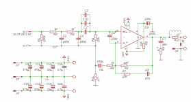
This schematic pretty much tells everything, it's a very simple board. It's a simplified version of the esp 33 board in many ways.
Some comments:
- C1 has to be a bipolar cap, voltage rating can be quite low since it never sees more than about 2V. A 10uF gives decent response.
- Q2-Q3, R6, R7, led1 is just a fault indicator. Not really needed. To be installed or not depending on what you want.
- all diodes are 1n4148. All resistors can be 1/2W.
- the optocoupler can also be the APV1121S
- D5 is a big TVS. Its working voltage must be a bit higher than your PS rails.
- with the version posted earlier, you have to be extra careful no to short the output lead to the binding post. Distances are a bit too small. I attach a new version of the board fixing that.
Attachments

Last edited:
- I've yet to really post a clear BOM, clear documentation, etc. It will not come before end of August as I'm quite busy these days (leading a group of pilgrims in Spain, I've only my phone with me).
- I promised to redo tests with the Millet interface to see if the 100hz artifacts really came from my testing setup. That will have to wait also until end of August.
- I also promised to redo the PS and DC protection boards that needed a quick touch up. I still have to post that too.
Hi 00940,
Did you have any luck with the 100Hz? Also, did you have final gerbers for the PS and DC boards? I'm looking to start a LM3886 soon and have followed this with interest (within the limits of what I understand).
Cheers
Neal
Picture?
Hello 00940,
thanks for your work and the gerbers and a happy new year! Even if the ripple comes from the amp itself and not from your test assembly - it's 105 db under signal and I would not bother too much with this.
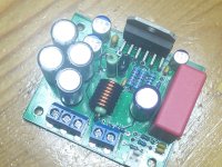
I just ordered some pcbs from JLCPCP. Could you please post a high resolution picture of an assembled board here? (would make the rebuild much easier, espacially concerning the mounting of the R/L Thiele combination).
Thanks in advance
Rüdiger
Hello 00940,
thanks for your work and the gerbers and a happy new year! Even if the ripple comes from the amp itself and not from your test assembly - it's 105 db under signal and I would not bother too much with this.
I just ordered some pcbs from JLCPCP. Could you please post a high resolution picture of an assembled board here? (would make the rebuild much easier, espacially concerning the mounting of the R/L Thiele combination).
Thanks in advance
Rüdiger
Not 00940, guessing he might be away, but here's mine (if the attachment works OK).
My inductor was calculated, not measured. It is 8 turns of 1.2mm wire on an 8mm former. The wire was too fat for the drill hole, so I soldered directly onto the resistor legs. My 2w resistors were slightly too long, so some careful forming of the leads was required.
My inductor was calculated, not measured. It is 8 turns of 1.2mm wire on an 8mm former. The wire was too fat for the drill hole, so I soldered directly onto the resistor legs. My 2w resistors were slightly too long, so some careful forming of the leads was required.
Attachments
I was kind of away; back home now but a bit overloaded. I'll try to snap a good pic on Wednesday.
Another option for the output RL network is to mount the resistor under the board if spacing allows.
Another option for the output RL network is to mount the resistor under the board if spacing allows.
inductor
Very helpful, thanks to sackot too!
Best regards
Rüdiger
I was kind of away; back home now but a bit overloaded. I'll try to snap a good pic on Wednesday.
Another option for the output RL network is to mount the resistor under the board if spacing allows.
Very helpful, thanks to sackot too!
Best regards
Rüdiger
I really need to do that write up...
Ok, here's the schematic. A BOM from Mouser is attached somewhere earlier but here is a generic one.
C1 - 2.2µ - various footprint available - mkp or at least mks
C2/C3 - 330p/50V - 2.5mm spacing - C0G
C4 - 220p/50V - 2.5mm spacing - C0G
C5 - 47p/50V - 2.5mm spacing - C0G
C6 - 100µ/50V - 5mm spacing, 10mm diam - bipolar
C7 - 56n/100V - 5mm spacing - mks
C8 - 100u/16V - 2mm spacing, 5mm diam - cheap electro
C9/10/11/12 - 470µ/50V - 5mm spacing, 10mm diam - decent electro
C13/14 - 22µ/50V - 3.5mm spacing, 8mm diam - polymer cap
C15/16 - 4.7µ/100V - 5mm spacing - X7R
R1 - 220K - 1/8W
R2 - 22k - 1/8W
R3 - 1k - 1/8W
R4 - 1k - 1/8W
R5 - 22k - 1/2W
R6 - 1k - 1/2W
R7 - 22K - 1/2W
R8 - 22K - 1206 smd
R9 - 4.7 - 2W
R10 - 10 - 2W
R11 - 4.7 - 1/8W
U$1 - LM3886
Input connector is 2.5mm spacing, power and output connectors are either 6.3mm faston or 5.08mm spacing screw terminals
Attachments
Just a couple of questions:Acknowledgement:
- This layout for the lm3886 has been made possible by the wealth of information given by Tom Christiansen, on his website neurochrome.com and on this forum (see especially this seminal thread, among many others).
- In this thread, I'm particularly indebted to the contributions of Mark Whitney and bozoc who pushed things in the right direction and corrected me when needed.
- under which open license the project is relased ?
- have you considered to post it @ Open Hardware RepositoryOpen Hardware repository ?
Have you got any relationship/collaboration with this project ?
LM1875/LM3886 based audio power amplifier
LM1875/LM3886 based audio power amplifier
It's not properly licensed. It's more of a "do what you want with it and if you have the courtesy to give attribution that's great but if not I don't care". The title just makes clear that everything needed for the project is actually public.
And no, no relation to that project.
And no, no relation to that project.
Ordered 10 boards from JLCPCB today for £5.71 inc postage. Thanks for your time spent on this, it's much appreciated.
Ordered 10 boards from JLCPCB today for £5.71 inc postage. Thanks for your time spent on this, it's much appreciated.
They are very good if you can keep pcb size below 100*100mm.
My pcb was 120mm by 100mm and they tripled the price.
Then I got hammered by customs charges.
Why don't adopt CreativeCommons BY or CC0 (aka Pubic Domain) license, then ?It's not properly licensed. It's more of a "do what you want with it and if you have the courtesy to give attribution that's great but if not I don't care". The title just makes clear that everything needed for the project is actually public.
-> Creative Commons — Attribution 4.0 International — CC BY 4.0
-> Public domain - Creative Commons
Establish some kind of collaboration could benefit both projects, then.And no, no relation to that project.
Hope that inspires !
Just google Gerber viewer, One of those results will be easyEda
Just out of interest I tried EasyEda on some of my gerber files.
The text came out quite badly.
Also some of the tracks were in the wrong place and shorting out.
- Home
- Amplifiers
- Chip Amps
- An open source layout for LM3886?