maybe I'm an old dino my self too (in my 67 y.o) 😉 as my pair of focal 2-ways (semi self made) speakers I have since '95 ? 94 ? or so (6L412 woofer/mid + TD90x tweeter + 6" passive crossed about 3.6KHz 12dB/oct) in a sealed box. I'm addicted to how they sound but.... "the better is the worst enemy of good". I'm almost always seeking around for a "better box" , but winkling also for full range drivers (my last purchase is a pair of MA CHP-90) and due to my limited (now) hearing ability to about a little higher of 14KHz. Your box is too attractive to me to ignore it. Will you give me (us) dimensions please ?......dinosaur........
Elias
Those are very nice drivers, must be good 🙂
If you look at the bottom of page 19 you will see the drawing for last iteration of the design.
If you look at the bottom of page 19 you will see the drawing for last iteration of the design.


Hello,
I am trying to model an 8" subwoofer.
I followed the steps starting at post#94.
Followed 3:1 tapering
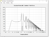
Attached are the results.
Kind request to validate the results and suggest a suitable folding scheme.
Thanks and regards,
Sumesh
I am trying to model an 8" subwoofer.
I followed the steps starting at post#94.
Followed 3:1 tapering
Attached are the results.
Kind request to validate the results and suggest a suitable folding scheme.
Thanks and regards,
Sumesh
Attachments

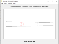
I would try to simplify the profile - straight sections, with a slightly smaller terminus, to extend the fundamental frequency lower.
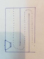
I would look at a slender "tower" design with the woofer near the bottom of the front. The closed end could be above the driver, and then the longer open end would go up behind the closed end, and then fold down on the back for the terminus. If the opening was at the bottom of the back, then you would get more room lift at the lowest frequencies. This would let you extend the bass lower and its roll off would keep it from being boomy.
You need to do iterations between an "actual" cabinet design that you can see how it is configured and whether it is buildable - and then you can know a Path distance from the center of the woofer to the center of the terminus opening on the outside of the cabinet. This will smooth the spikes.
Nailed it. Add the red distance as ‘path’ in your sim as Neil stated and build it 😀
nice subwoofer Hifiaudio👍🏼
nice subwoofer Hifiaudio👍🏼
Attachments

Last edited:
Thank you.I would try to simplify the profile - straight sections, with a slightly smaller terminus, to extend the fundamental frequency lower.
I would look at a slender "tower" design with the woofer near the bottom of the front. The closed end could be above the driver, and then the longer open end would go up behind the closed end, and then fold down on the back for the terminus. If the opening was at the bottom of the back, then you would get more room lift at the lowest frequencies. This would let you extend the bass lower and its roll off would keep it from being boomy.
You need to do iterations between an "actual" cabinet design that you can see how it is configured and whether it is buildable - and then you can know a Path distance from the center of the woofer to the center of the terminus opening on the outside of the cabinet. This will smooth the spikes.
I shall make a drawing a and post here.
Thanks for the references.Nailed it. Add the red distance as ‘path’ in your sim as Neil stated and build it 😀
nice subwoofer Hifiaudio👍🏼
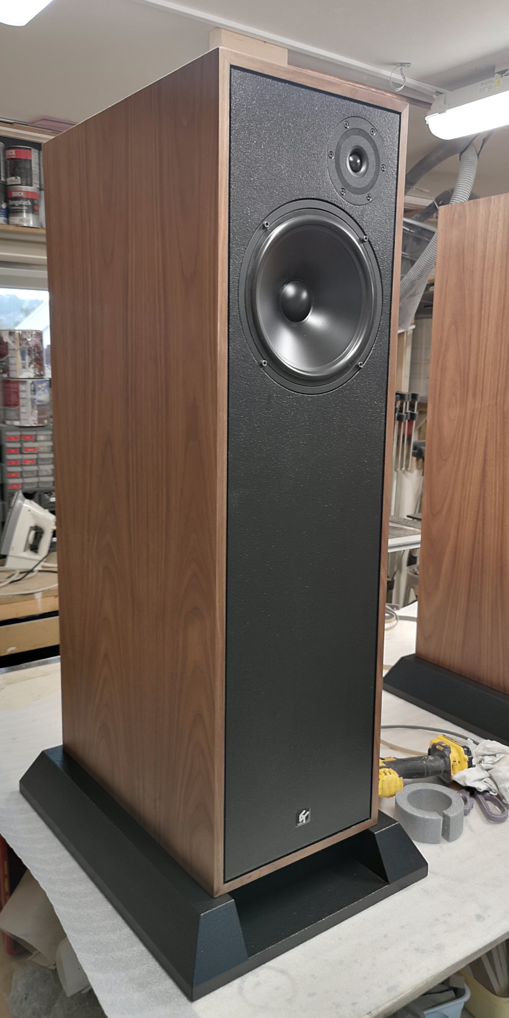
Beautiful work, cbarth! Amazing looking speaker.
Can you confirm what drivers you are using and what the crossover design looks like (or is it TBD)?
From an earlier post I think you said Vifa P21 and Hiquphon OW5?
You mention the P21 is old school but has some very nice characteristics not found in today’s newer drivers. Would like to understand more about this.
Congrats on a super build!
The old Vifa units (P13, C17, P21 etc.) tended to have relatively smooth, extended axial responses with a progressive HF rolloff. So in a sense, it could make filter design easier since, notwithstanding impedance correction, you could get away with relatively simple filters assuming you don't mind a higher crossover frequency & the inevitably dodgy polars that come with it. The latter is meant as an observation rather than a criticism since it's exactly what Harbeth, Spendor & many others do, and while they certainly aren't above critique, they do a lot right within their intended context. Be that as it may, there aren't all that many drivers of this type around now. Some, but the old Vifas were exceptional in this sense.
cbarth, What's that textured finish you used on the front baffle? Love the textured contrast against the veneer.
The old Vifa units (P13, C17, P21 etc.) tended to have relatively smooth, extended axial responses with a progressive HF rolloff. So in a sense, it could make filter design easier since, notwithstanding impedance correction
Single cap on these with P13 (before King).

dave
cbarth, What's that textured finish you used on the front baffle? Love the textured contrast against the veneer.
I wonder if it’s classic Duratex applied with a roller brush? I think any relatively high viscosity matte black latex paint could work here.
I like that finish too and had it applied on a couple of my speakers.
Thank you, Mr. Neil Blanchard.I would try to simplify the profile - straight sections, with a slightly smaller terminus, to extend the fundamental frequency lower.
I would look at a slender "tower" design with the woofer near the bottom of the front. The closed end could be above the driver, and then the longer open end would go up behind the closed end, and then fold down on the back for the terminus. If the opening was at the bottom of the back, then you would get more room lift at the lowest frequencies. This would let you extend the bass lower and its roll off would keep it from being boomy.
You need to do iterations between an "actual" cabinet design that you can see how it is configured and whether it is buildable - and then you can know a Path distance from the center of the woofer to the center of the terminus opening on the outside of the cabinet. This will smooth the spikes.
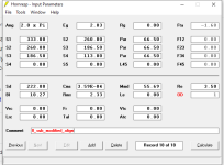
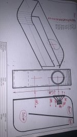
I have tried as per your directions. Planning for a 3:1 Taper, Sd = 222 sq cm: S0 = 326 sq cm. Terminus area = 111sq cm ( half of sd).
Request suggestions for improving the design.
I do not know how to set the path length.
I believe that the path length would be zero for the drawing below.
Thanks and regards,
Sumesh
Attachments
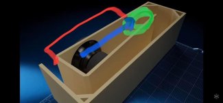
This is another folding method i saw in www.diysubwoofers.org by Mr. Brian .
Wish to know which one is more suitable for subwoofer.
Wish to know which one is more suitable for subwoofer.
Attachments
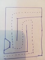
No, the path is from the center of the woofer to the center of the terminus opening - on the outside of the cabinet. So if the cabinet is a foot wide, and 2 feet front to back, the Path would be 3 feet for that drawing. The Path is entered in the Cabinet section of the Wizard.Thank you, Mr. Neil Blanchard.
I have tried as per your directions. Planning for a 3:1 Taper, Sd = 222 sq cm: S0 = 326 sq cm. Terminus area = 111sq cm ( half of sd).
Request suggestions for improving the design.
I do not know how to set the path length.
I believe that the path length would be zero for the drawing below.
Thanks and regards,
Sumesh
In order to know which is better, you need to dive into Hornresp and when you get the response close - draw a dimensioned drawing, to see what those dimensions require in order to be built. It may be that the woofer moves up the front of the cabinet if the length of the closed end needs to be shorter. Once you get a dimensioned cabinet drawing - feed those volumes and length back in to Hornresp and see how it works. If you need more volume with the same length, make the cabinet wider.
This process is a back and forth between a drawing of a buildable cabinet, and the Hornresp model. And with a dimensioned drawing, you can get the Path length you need to smooth the spikes and dips out of the response.
Last edited:
- Home
- Loudspeakers
- Full Range
- An Improved Transmission Line Alignment