Yeah, and did the matching 'finished' comparison initially I normally use to decide which is the better overall choice for the intended app, but decided the undamped matching alignments was a better overall 'teaching' choice only to forget to delete HR's recently added BR's QL = 7 default. 🙁
I assume due to each requiring a different math routine, i.e. BR assumes a box having a ~uniform particle density whereas the horn segments requires wave equations same as the BR's vent.don't know why you can not get the result using the horn segment
... HR's recently added BR's QL = 7 default. 🙁
That one threw me for a loop when getting back into HR recently, until I noticed it and brought its value up a bit.

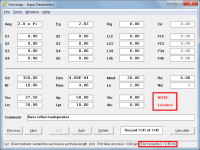
1. Set QL to Lossless in the bass reflex design as shown in Attachment 1.Simulating the BR how it was intended, like yours, gets the same expected phase response, don't know why you can not get the result using the horn segment to make a roughly physically equivalent BR.
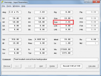
2. Add internal end correction to the front loaded horn design by either increasing L12 or adding a second segment as shown in Attachment 2.
The results for both designs will now be identical.
Attachments
did you test it? QL has little effect, horn lengths could be doubled or halved but also has little effect on the phase response.
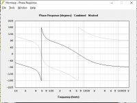
Yes. Did you test it? 🙂 With the described modifications, the results are identical, but the phase shows a 180 degree phase shift between the two cases. The reason is simple; the bass reflex case takes the direct radiation off the front of the diaphragm, the horn version off the rear. You can see it in the schematic. See attachment.did you test it? QL has little effect, horn lengths could be doubled or halved but also has little effect on the phase response.
Changing QL and horn lengths will mainly change the response (and hence the phase) around the port resonance frequency. There's a noticeable (several dB) difference between lossless and QL=7 at the port resonance for my example, and doubling the length of the 10cm horn segment changes the port frequency by 12Hz or so.
Basically, Hornresp doesn't take the inner length correction into account when using horn segments, but does so when using the vented rear chamber option. So the length correction must be added manually when using horn segments. But only the inner one, as the outer one comes from the radiation impedance which is always included.
Attachments
So, I follow these thoughts and can see where it is going. All for revisiting and improving. But, It still sends me back to low Q sealed boxes. .6 or lower if you can get it. Only some drivers can reach "critical Q" of .5 in a reasonable box.
I still see a TL as an older concept from before we understood how an excited resonator works. Their advantage in being broad band and tolerant of driver variation just no longer seems to be needed. We can now engineer drivers that behave in sealed boxes because we know the target. Just my experience here.
I still see a TL as an older concept from before we understood how an excited resonator works. Their advantage in being broad band and tolerant of driver variation just no longer seems to be needed. We can now engineer drivers that behave in sealed boxes because we know the target. Just my experience here.
In the old days TLs were ceratinly in a limited design space, often mis-defined by those who based everything on the title of Bailey’s article but modern modelers as exemplified by MJK have greatly expanded quarter-wave design space and the term TL has grown to cover much of that space.I still see a TL as an older concept from before we understood how an excited resonator works.
dave
Quite. For better or worse the term 'transmission line' became a rather meaningless generic 'catch all' by the late '60s. The OP, with the very best of intentions, started the thread unaware that a huge amount of work had been done in the field & its physics for several decades and there was nothing new about an offset driver line. If it helps make some others aware of that fact though & guide them away from widespread misconceptions, it's all to the good.
As for a TL being 'an older concept from before we understood how an excited resonator works' they are in fact well understood, but the continued popularity of misinformation (statements like that being a good example) does limit their use in a wider sense. Moreover -they are 'excited resonator' themselves -just employing eigenmodes (standing waves) rather than Helmholtz (cavity) resonance, or in certain cases a combination thereof. Nor are they necessarily any more (or less) tolerant of driver variation than any other box alignment: it depends on the specifics of the design. In a similar vein, we can 'engineer drivers that behave' in any kind of general box type. Nothing mysterious or profound about that -it's been done for decades. Due to the current, if rather long-standing fashion, a majority of modern drivers are predominantly designed & optimised for some kind of vented box load however rather than sealed boxes, assuming a reasonably extended LF response is desired.
As for a TL being 'an older concept from before we understood how an excited resonator works' they are in fact well understood, but the continued popularity of misinformation (statements like that being a good example) does limit their use in a wider sense. Moreover -they are 'excited resonator' themselves -just employing eigenmodes (standing waves) rather than Helmholtz (cavity) resonance, or in certain cases a combination thereof. Nor are they necessarily any more (or less) tolerant of driver variation than any other box alignment: it depends on the specifics of the design. In a similar vein, we can 'engineer drivers that behave' in any kind of general box type. Nothing mysterious or profound about that -it's been done for decades. Due to the current, if rather long-standing fashion, a majority of modern drivers are predominantly designed & optimised for some kind of vented box load however rather than sealed boxes, assuming a reasonably extended LF response is desired.
I find it odd, as I came to TLs as a lossy concept from the Kapellmeister kind of 'ideal', I.e. losing the wave.
(I have to admit that should my bricks and mortar allow me facility to build my last ever speaker system, I'd love IB Subs, and lossy Kapellmeister style satellites, from 100Hz up)
This was never akin to an electrical transmission line, which is matched to the load to return reduced transmission loss, but perhaps more akin to an attenuation stub, and naturally tends to a theoretical IB result. Except that we may now be converting the energy we don't want, in a 'better' way.
MJK work really opened up the world, for me, at that time.
Not only was it not a TL in the olde worlde sense, but had more akin to an electrical matching network. Oh...I mean....a matched transmission line.
🤣
In the end it still comes down to Vented or IB/CB, even when hornloaded
I feel TLs began maturing toward the end of the '90s, with the likes of Augspurger, and the other guy I'm sure Dave could remind me the name of.
While I'm still far from being all-knowing about loudspeaker design and tech, the most helpful thing I've learned has got to be how most - if not all - LF schemes/topologies/loads are a continuum, with so many designs falling in the grey areas between the "pure" types.
I feel TLs began maturing toward the end of the '90s, with the likes of Augspurger, and the other guy I'm sure Dave could remind me the name of.
Martin King -see www.quarter-wave.com
Yes, it was largely George and Martin who were responsible for doing some properly conducted experimenting, then breaking the maths / physics down into a form suitable for widespread use. We've a couple of guys on the forum who did similar work back in the '70s too, but it was for personal use / graduate teaching / projects IIRC & they didn't distribute given the rather more limited means. There are others who had the basics down prior to that too of course, albeit without the detailed refinements / ability to assess details in advance.
Last edited:
Right, they're basically all on some variation of a scale or scales. GM and I for e.g. view most chambered back-horns as more or less extreme variations on the vented box theme. There aren't all that many 'pure' types when you get right down to it & the sooner that notion is rejected (at least in my experience) the easier it is to identify advantages or issues in a given box & address them effectively.While I'm still far from being all-knowing about loudspeaker design and tech, the most helpful thing I've learned has got to be how most - if not all - LF schemes/topologies/loads are a continuum, with so many designs falling in the grey areas between the "pure" types.
Augspurger released his paper on TLs at AES (Sept?) 99 in NYNY. I was there. At the time i was workign with Maertin to get his stuff on line. So 2 accurate modelers based on 2 different analogies giving pretty much the same results at the same time. MJK continued to develop things, Augspurger stalled, so has become an also ran as far as TL modeling goes.I feel TLs began maturing toward the end of the '90s, with the likes of Augspurger, and the other guy I'm sure Dave could remind me the name of.
MJK opened up a huge new design space, and, as mentioned by Scott, TL has often beome. generic name for quarter or half wave resonant designs.
dave
No, I don't recall Martin until later. I'm going back to the Speaker Builder magazine days.Martin King
- Home
- Loudspeakers
- Full Range
- An Improved Transmission Line Alignment