Hi Eric,
The acoustic path length is the length of the shortest acoustic path between the two outputs (assumed to be point sources). For a closed-mouth three segment offset driver design such as yours, Hornresp assumes that the cabinet is not folded in any way, and automatically calculates the path length as L23, which for your design is 100 cm. At the moment it is not possible to manually set the path length to some other value, but this will be changed in the next release.
Setting the path length to zero does not change the physical positions of the port and driver in the design, it just means that the point source radiators are assumed to be very close together for the purposes of calculating the combined response. For example, in a folded design it is possible to have the driver and port close together, even though the transmission line separating them may actually be quite long.
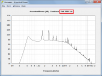
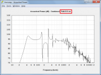
Changing the position of the driver and/or port in LATL will change the results, but not the path length assumption. While I don't have access to LATL myself, it would seem that the program assumes the two outputs are co-located for the purposes of calculating the combined response. Although you won't be able to do it yourself until the next release, setting the path length to zero in Hornresp produces the combined response shown in Attachment 3, which is very similar to your LATL result, up to the high frequency roll-off point. The difference between the Attachment 1 (100 cm path length) and the Attachment 3 (0 cm path length) responses shows why it is important to take the actual path length into account, and not just simplify things by using 0 cm.
Kind regards,
David
Does path length simply mean the distance between the driver and the port?
The acoustic path length is the length of the shortest acoustic path between the two outputs (assumed to be point sources). For a closed-mouth three segment offset driver design such as yours, Hornresp assumes that the cabinet is not folded in any way, and automatically calculates the path length as L23, which for your design is 100 cm. At the moment it is not possible to manually set the path length to some other value, but this will be changed in the next release.
If I'm understanding he meaning of "path length" correctly, setting the path length to zero would mean placing the port and driver at the same location in the line, is that correct?
Setting the path length to zero does not change the physical positions of the port and driver in the design, it just means that the point source radiators are assumed to be very close together for the purposes of calculating the combined response. For example, in a folded design it is possible to have the driver and port close together, even though the transmission line separating them may actually be quite long.
I don't think LATL assumes a zero path length, because moving the driver and/or port to different locations definitely changes the results
Changing the position of the driver and/or port in LATL will change the results, but not the path length assumption. While I don't have access to LATL myself, it would seem that the program assumes the two outputs are co-located for the purposes of calculating the combined response. Although you won't be able to do it yourself until the next release, setting the path length to zero in Hornresp produces the combined response shown in Attachment 3, which is very similar to your LATL result, up to the high frequency roll-off point. The difference between the Attachment 1 (100 cm path length) and the Attachment 3 (0 cm path length) responses shows why it is important to take the actual path length into account, and not just simplify things by using 0 cm.
Kind regards,
David
Attachments

Setting the path length to zero does not change the physical positions of the port and driver in the design, it just means that the point source radiators are assumed to be very close together for the purposes of calculating the combined response. For example, in a folded design it is possible to have the driver and port close together, even though the transmission line separating them may actually be quite long.
David,
Ah, now I think get it. I figured I was missing something. So, if I have it right now, path length is effectively the separation of the two radiators when viewed from the outside of the cabinet, rather than the inside.
I think your simulation in HR with pathlength set to zero pretty much proves your hypothesis that LATL assumes a zero path length.
Thanks, I really appreciate your explanation and demonstration of this.
Eric
path length is effectively the separation of the two radiators when viewed from the outside of the cabinet, rather than the inside.
Correct.
Note that in most cases the path length is not equal to the difference in the distances from each point source to the observer, which confuses some people.

This seems a bit of a jumbled thread, with several themes, but originally was about a simple means of devising an easy build TL sub.
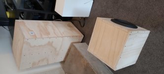
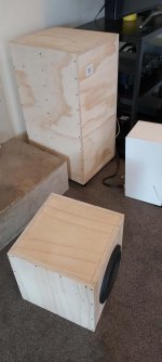
Being a novice to HR I decided this was for me. So I followed John's advice and came up with a large box, typical TL, that fits my RSS390 Dayton 15-inch driver, with a 3:1 taper.
It replaced the Pipeline that the missus wasn't fond of. I kind of liked the alien in the room theme but she is not a sci fi fan. So it had to go.
Nor is she especially fond of the new box but I did warn her she would be replacing a storm water system with a coffin for a large animal. She is beyond caring at this point, I get the feeling. Though when she leaves, I guess really she did actually mind. But then give and take. She likes to run, I like to build aesthetically challenging subs.
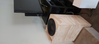
Anyhow, I tried the TL out first with the driver upfiring and this didn't really fire on all four, but when I turned it over, a much better response, more room gain then.
Compared with the pipeline (3.4m vs 2.6m) this doesn't quite hit the low notes as well - I think the pipeline was hitting low 20s; this feels more like 25-30Hz in room - but otherwise this sounds better, more articulate and less one-notey. With the pipeline the drivers were at the beginning of the line; in the latest iteration the driver is about one-third the way down.
I dont have measurement tools so cannot post power response graphs sorry. But thanks PB (John) for taking the time to show us learners how it's done with HR.
Working on a TH next, a slightly smaller enclosure but back to pipes; this one shouldn't be quite so visually affronting.
Being a novice to HR I decided this was for me. So I followed John's advice and came up with a large box, typical TL, that fits my RSS390 Dayton 15-inch driver, with a 3:1 taper.
It replaced the Pipeline that the missus wasn't fond of. I kind of liked the alien in the room theme but she is not a sci fi fan. So it had to go.
Nor is she especially fond of the new box but I did warn her she would be replacing a storm water system with a coffin for a large animal. She is beyond caring at this point, I get the feeling. Though when she leaves, I guess really she did actually mind. But then give and take. She likes to run, I like to build aesthetically challenging subs.
Anyhow, I tried the TL out first with the driver upfiring and this didn't really fire on all four, but when I turned it over, a much better response, more room gain then.
Compared with the pipeline (3.4m vs 2.6m) this doesn't quite hit the low notes as well - I think the pipeline was hitting low 20s; this feels more like 25-30Hz in room - but otherwise this sounds better, more articulate and less one-notey. With the pipeline the drivers were at the beginning of the line; in the latest iteration the driver is about one-third the way down.
I dont have measurement tools so cannot post power response graphs sorry. But thanks PB (John) for taking the time to show us learners how it's done with HR.
Working on a TH next, a slightly smaller enclosure but back to pipes; this one shouldn't be quite so visually affronting.
Attachments
Last edited:
You started the hobby too late, I didn't marry until I had a total of ~131 ft^3/3710 L of stereo corner compression horns, so came as part of the 'package' 😀.
GM
GM
I have a pair of 18 inch woofers vented into the ceiling in an IB configuration.
I have always wondered what would happen if I changed things so it was a low tuned TL to support the 16-32 hz range. The nulls higher up in the frequency range kept me from going there. I use the 18s up to 300 HZ in this case. This thread gives me hope if I can support the lower end and avoid dips.
I have always wondered what would happen if I changed things so it was a low tuned TL to support the 16-32 hz range. The nulls higher up in the frequency range kept me from going there. I use the 18s up to 300 HZ in this case. This thread gives me hope if I can support the lower end and avoid dips.
The benefit of an addition is a dedicated listening room; it can be designed to work properly from the outset. I have only ever tried to optimise rubbish rooms and it's just hard work.
The only time it has gone well was by happenstance. Years ago we bought a small beach house; it has a highly irregular ceiling with high and low sections in the main room and you can plonk speakers almost anywhere and they sound great.
But all the rectangular prisms I've worked with have simply been like speaker boxes; resonance chambers. In our current place, the sound completely changes when you move your head forward six inches away from the rear wall. And that's pretty much right where the listening position is. But there is no alternative in this particular room.
So count yourself lucky!
According to a room guy i met at AES 99, the single biggest thing you can do is slope the ceiling. Makes a huge differenc ein my room.
Use irrational numbers for the dimensions (then rationaize to your build materials). It needs to be solid, doors and windows are acoustic leaks, sometimes they help.
Perhaps some empty space behind the speakers to allow for helmholz absorbers in the wall if needed.
dave
Use irrational numbers for the dimensions (then rationaize to your build materials). It needs to be solid, doors and windows are acoustic leaks, sometimes they help.
Perhaps some empty space behind the speakers to allow for helmholz absorbers in the wall if needed.
dave
That sounds pretty much like the room I was describing; tall sloped ceilings in one part, flat in another, asymmetric, carpet over concrete floor, and a big brick fireplace behind the speakers. If it's true that almost half of what you hear is the room, then if you can eliminate or mitigate the bad half, it sure makes the resulting sound much more satisfying.
According to a room guy i met at AES 99, the single biggest thing you can do is slope the ceiling.
Use irrational numbers for the dimensions (then rationaize to your build materials). It needs to be solid, doors and windows are acoustic leaks, sometimes they help.
Perhaps some empty space behind the speakers to allow for helmholz absorbers in the wall if needed.
dave
Indeed! My first house's main level had a cathedral ceiling to accommodate 108" high speakers, the acoustics was an intentional bonus and this house would have a one side cathedral ceiling also if my health hadn't been so bad for decades now.
Right on! The first house had $$ windows designed for the job, but this one I had to make-do with cheapest sash windows I could find and added inexpensive storm windows at ~1/4 the price IIRC and have worked nearly as good with the downside being the extra maintenance work. Door assemblies are $$ exterior fire rated solid core. The seals that come with this type are good enough IME.
FWIW, I'm a big fan of LEDE, so like speakers very near/at the sound wall configuring it all to try and get the first reflections behind my ears [horns help alot], then make the rest as diffuse as practical, using bookcases loaded with all manner of things to create reflections, cavities, etc..
GM
How does one translate Hornresp's schematic diagram into actual cabinet dimensions? If S1, S2, S3 are the cross-sectional areas along the line (red in the diagram), then what are the actual x, y values?
I may be overthinking (or not thinking), but when I place the driver in the box it will change the box volume and Fs, so then I will need to adjust length, but this then changes volume, Fs, so I have to adjust length, which again volume, Fs... and I get into this vicious cycle.

I may be overthinking (or not thinking), but when I place the driver in the box it will change the box volume and Fs, so then I will need to adjust length, but this then changes volume, Fs, so I have to adjust length, which again volume, Fs... and I get into this vicious cycle.
This post I made from eighteen months ago, basically describes how you can simplify the process of building transmission lines:
An Improved Transmission Line Alignment.
In a nutshell, David McBean made a new version of HornResp that allows for 'stepped' transmission lines. Basically the diameter of the cross-section can go up in 'steps' instead of going up gradually.
This simplifies building a transmission line, because you can make transmission lines where the walls are parallel, and the segements of the line go up in steps, instead of going up smoothly.
allows for 'stepped' transmission lines
It couldn’t model Olsen/Nagaoka style horns/TLs before? That would be a very important upgrade.
Can you put the expansion that occurs at bends in the horn path?
dave
How does one translate Hornresp's schematic diagram into actual cabinet dimensions? If S1, S2, S3 are the cross-sectional areas along the line (red in the diagram), then what are the actual x, y values?
You set x, y from CSA, HR sims are cylindrical and you have to account for any net volume [Vb] losses due to driver
GM
It couldn’t model Olsen/Nagaoka style horns/TLs before? Can you put the expansion that occurs at bends in the horn path?
AFAIK it always ~could if you work out its flare frequency and factor. Of course it won't be perfect due to its stepped pipes Vs a smooth expansion, but good enough for simming purposes; otherwise AkAbat.
GM
HR sims are cylindrical and you have to account for any net volume [Vb] losses due to driver, bracing, vent
Oh! Ok, thanks! I wrongly thought the schematic diagram was modelling a rectangular line, probably confused because I read somewhere PAR means two parallel walls + 2 linear tapered walls.
But like you say, whatever gets you similar volume and length is probably close enough.
Right, we used conical till me and a few others said it was parabolic and confirmed by DMB, but sims are close enough to use.
Some nitpicking re sims are inaudible plus HR doesn't factor in real world electro-acoustical-mechanical losses except when certain options are used and even then can be just approximations, so another reason not to be too anal about it.
A real world HR assumption one needs to keep in mind is corner loading [0.5 pi], which is parabolic and goes to infinity as far as loading is concerned, so instead of +9 dB it's very room height, construction dependent. In my room I barely get wall/floor loading [1.0 pi] due to stick built w/'floating' [suspended] floor.
GM
This thread has been very, very helpful,along with the FB transmission line group. I will post my "results" from working in Hornresp and the CAD program I use for work, called DataCAD.
I am contemplating building a TL for an 8" 2-way speaker.
A little background - I own a pair of Linaeum LT1000 speakers, which are a transmission line cabinet. It is really simple - total length is about 5' with a single 180 degree bend at the botto, of the cabinet, up the back to an opening, right below the open back of the Linaeum TLS tweeter. The TLS driver is actually a midrange / tweeter - it crosses over to the 8" woofer at 440Hz.
This speaker sounds phenomenal - it is the best I have ever heard in my ~44 years of hifi. So I actually have 2 goals - I'd like to build a new cabinet for the LT1000, because my son has a pair of Linaeum LS2 speakers - that use the same extremely rare TLS tweeter. This is a 6" high monopole version.
My other goal is to build a similar cabinet, but use the relatively common Radio Shack Linaeum tweeter. This is a 1.5" high dipole version of the Linaeum tweeter and it is likely crossed over at a much more common 2kHz.
I settled on this woofer:
DAYTON AUDIO RS225P-4A
Sd - 213.8 sq cm = 33.1sq in
Fs = 37.7Hz Qts = 0.38 Mms = 25 grams
Here is what I *think* is the final design, that went through a lot of iterations - comparing the Hornresp model to the drawing, and then changing the drawing - and then putting that data into the model. With the help of folks here and at the DIY Audio thread linked in this thread - here's what I have arrived at:
Shared album - Neil Blanchard - Google Photos
Shared album - Neil Blanchard - Google Photos
(Is there a way to upload and post pictures?)
- Home
- Loudspeakers
- Full Range
- An Improved Transmission Line Alignment