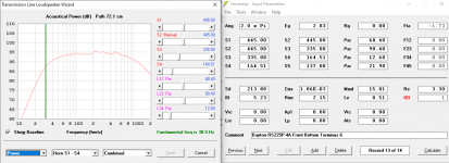
How are you getting the fundamental frequency to show?
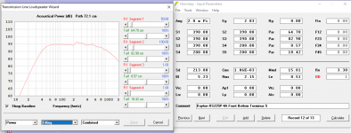
In the LS Wizard, choose to display "power", then double click on the graph and a vertical green line will appear at the fundamental. Bring the cursor near the green line and the number will display in place of the horn length.
Eric
Question for folks: are these acting as low pass filters? Will they roll off the higher end of the woofer's output, as shown on the response?
Others should really answer this. But my understanding is "not necessarily." That is, you should really only be having faith in the low frequency response of this model, and not the high end. When I model full range drivers in HR they show similar roll off above about 800 Hz but in real life not so much.
Eric
Eric, I want to thank you again - you have made this a much less fussy build, and it is arguably better, in several ways.
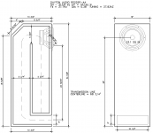
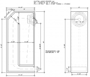
I recreated your drawing, and I like how you count the transition as L34 - that makes a lot of sense. I interpret the L12 slightly higher because that is where the center of the driver is sitting, so it is as close to the top as possible. And I left the 4" chamfer panel at the top rear - this is to reduce the length of the top, for the tweeter's backwave; and to reduce any sound reflection back out through the woofer cone.
Bottom line is I got virtually the same response as you. The only tweak that seems to help extend and lift the lowest shelf a *smidge* is to reduce the fill in the first section to 50. This leaves the small bumps virtually unchanged.
I then tried a 10" wide cabinet (vs the one at 12"), and leaving the section areas identical - this lengthens L23, L34, and L45 a touch - and guess what? It gets smoother and a touch deeper! I did use 67 filling in L12 on this one, but who's counting?
The mouth velocity is under 1m/sec - great! These have slightly higher impedance than the designs I did, and that helps, too.
The biggest difference between these and the ones I just uploaded, is the low knee is larger radius so-to-speak - it starts a bit higher up and rolls off over a wider range. So it may not have the "flat" response as low - but on the other hand, they hit 74dB at 20Hz vs about 70dB for the ones that I had done. I have a feeling that room lift will mean the broader rolloff is moot. And an extra 4dB at 20Hz is significant.
Attachments

Last edited:
This Hornresp program is *deep*. The 10"x 16.5" version has a fundamental frequency of 35.2Hz! I like that!
And I was leaning toward what you say about the higher frequency output - the great thing about TL speakers is they let the driver act closer to an open baffle at the upper end, and gradually add mass loading at the bottom end.
So you get more bass and better bass out of a smaller / fewer drivers than any other speaker design. This means lower Mms and less complexity - and better value. Not having to deal with subwoofers and getting all but the earthquake stuff at high volumes - is amazing!
I modded my LT1000 cabinets with 30" long 3"x 8 3/4" extensions on the back - and the low bass comes through *when it is present* like I have never experienced before. And that is with a 33 year old flawed design (pretty short at ~60" and a ~5dB dip in the 150-200Hz range); with an add on fix.
Edit: if the terminus opening is reduced to 130cm2 - 1/4" reduction on all sides, down to a 2 1/2" x 8" opening, the bumps are reduced and the fundamental frequency drops to 34.7Hz. I decreased the fill in section 1 to 45 and section 2 to 85. I think we have a winnah!
Attachments

Last edited:
That is, you should really only be having faith in the low frequency response of this model, and not the high end.
Right, as I've posted elsewhere lately:
T/S theory peters out at the driver's effective upper [Fhm], lower [Flc] mass corners, so any bandwidth response plot beyond these points are strictly due to [inputted] inductance [mH] and/or mass roll off, with on-line freeware generally just flatlining it:
Fhm = 2*Fs/Qts'
Flc = Fs*Qts'/2 [normally never used]
Qts' = 2*Fs/Fhm
Qts' = Qts + any added series resistance [Rs]: HiFi Loudspeaker Design
[Rs] = 0.5 ohm minimum for wiring, so may be higher if a super small gauge is used as a series resistor
GM
I then tried a 10" wide cabinet (vs the one at 12")
The mouth velocity is under 1m/sec - great!
The biggest difference between these and the ones I just uploaded, is the low knee is larger radius so-to-speak -
FWIW, 'sound is round' and so is all simmed sections and of course unfolded, so not sure how accurate such a comparison is, so one for DMB. Bottom line, net volume [Vb], taper rules.
WRT input, ideally need to change [EG] to reflect a nominal 4 ohm load and add a 0.5 ohm in [Rg].
Hmm, need to find its vent mach at whatever power the driver can safely handle, which isn't much, so it will still be low, just somewhat higher than 1 m/s.
GM
My experience is that in a TL those 45° corners do not improve the response. there is a reflection from the bottom, that gets directed to the speaker so it is better to put damping material on the top. It will have little effect on the fundamental.
I construct a labyrinth for the last 1/3 with a couple of 180° bends which effectivly limit the line output above 400Hz but do not affect the fundamental.
Very effective way speaker mounting at 1/3 to suppress the 3rd harmonic, but it dampens a bit the fundamental, around 0.88(cos30°)
I construct a labyrinth for the last 1/3 with a couple of 180° bends which effectivly limit the line output above 400Hz but do not affect the fundamental.
Very effective way speaker mounting at 1/3 to suppress the 3rd harmonic, but it dampens a bit the fundamental, around 0.88(cos30°)
Last edited:
FWIW, 'sound is round' and so is all simmed sections and of course unfolded, so not sure how accurate such a comparison is, so one for DMB. Bottom line, net volume [Vb], taper rules.
WRT input, ideally need to change [EG] to reflect a nominal 4 ohm load and add a 0.5 ohm in [Rg].
Hmm, need to find its vent mach at whatever power the driver can safely handle, which isn't much, so it will still be low, just somewhat higher than 1 m/s.
GM
Right, thanks! I reduced the opening to 2.5" x 8" (1/4" reduction on each side) and at 100 watts (18.7V ?) the mouth velocity is about 9.5m/sec. And the fundamental frequency drops to 34.7Hz. This is over 110dB SPL predicted, which is plenty.
The chamfered corner is there for two other reasons - to reduce the top surface area so the dipole tweeter has a bit less to reflect off (there may need to be felt there, anyway) - and to reduce the reflections of higher frequencies back out through the woofer cone. The top part of the vertical baffle will want to have damping material for this purpose, as well.
I am going to try a version of this enclosure for the 8 ohm version of this Dayton Audio woofer - the RS225P-8A. It has a slightly greater Xmax of 7mm, a larger Vas of 68.8 liters, and a lower Le of course. The Qts is 0.34 (vs 0.38 for the 4 ohm). It has a slightly lower Mms of 23.6 grams (vs 25gm for the 4 ohm) and a lower Fs of 31.6Hz (vs 37.7Hz of the 4 ohm). And the main difference is 89.9dB efficiency (vs 92.9 for the 4 ohm). This is a better match for the 1.5" high Radio Shack made Linaeum tweeter.
The 8 ohm driver is included in the Hornresp export file in an earlier post. Parts Express has both the 8 and 4 ohm drivers on sale for $50, by the way. They have a well designed paper cone, that has two other materials blended in. The low Mms of these drivers is a very good thing.
Last edited:
Dropping in the 8 ohm Dayton woofer barely changes anything. I needs slightly less filling in the second section (~55) and keeping the 45 in the first section. The fundamental frequency rises to 35.2Hz ... which is great!
Diaphram displacement is actually reduced to a maximum of 4mm (vs 6mm for the 4 ohm).
This seems to be a somewhat forgiving / flexible design. I really appreciate the folks here for steering me along.
My plan is to use the miniDSP 2x4 HD as an active crossover. This is what I am using on my Linaeum LT1000 speakers, and they sound better than anything I have heard, in 40+ years. This requires biamping - I am using a Schiit Audio Vidar on the woofers - having the amp directly driving the woofers is great sounding. I have my venerable B&K ST140 (recently recapped) on the amazing Linaeum TLS tweeter / midrange. The crossover is at 440Hz with 4th order Linkwitz Riley - actually I have a 3rd order on the tweeter, and left the 22uF capacitor in line to get effectively 4th order, and protect the super rare TLS driver. For our friend Justin Case.
Last edited:
The Baltic birch ply available is presumably metric in dimension, 5x5 ft is really 150cmx150cm. Measure the thickness as it's not 3/4 of an inch mine is 18mm. Here in Montréal we can get 4' by 8' sheets in a specialist lumber yard not at a big box store. Avoid accumulated error!
Also important is the quality of the panel saw/operator. At my fav yard, Langevin et Forest, the workers in the cutting shed do only this and the saw is well maintained.
Right - 18mm is closer to 11/16". I will build to the interior dimensions. And I will adjust the drawing to be 18mm thickness. The 150cm square is 4'-11 1/16" - CAD is good at this sort of thing, 🙂
My brother and I know a cabinet maker, and we will ask him for a good supplier.
My brother and I know a cabinet maker, and we will ask him for a good supplier.
The information I got, for here in the US is they have 15mm (9/16") and 19mm (3/4") thicknesses. I will call the local suppliers to confirm the sheet size; at this point I am assuming 150cm (4'-11") square.
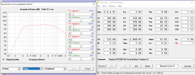
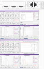
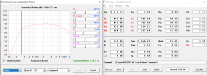
I have updated the enclosure for the Dayton Audio RS225P woofer. It is slightly taller, and I shifted the vertical baffle an inch back, so the closed end is 445cm2 and the main part of the open end is effectively tapered to 335cm2. The last section starts at 164.3cm2 and the opening is 137cm2.
There are essentially no dips anymore, and the peaks are smaller and all above 200Hz. (The active crossover will be able to effectively cut these even further with DSP EQ.) And amazingly, the fundamental frequency - is 30.5Hz !!
Question: I am thinking that I will use vertical braces - for accuracy, should I subtract their thickness from the model, to see if they change anything?
I may use part of the remaining part of the plywood sheet for a plinth, but I think that stability may well be excellent, and not require it.
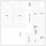
I am planning on the sides covering the ends of all the other pieces, and I am thinking that small rabbet joints will be plenty.
I have updated the enclosure for the Dayton Audio RS225P woofer. It is slightly taller, and I shifted the vertical baffle an inch back, so the closed end is 445cm2 and the main part of the open end is effectively tapered to 335cm2. The last section starts at 164.3cm2 and the opening is 137cm2.
There are essentially no dips anymore, and the peaks are smaller and all above 200Hz. (The active crossover will be able to effectively cut these even further with DSP EQ.) And amazingly, the fundamental frequency - is 30.5Hz !!
Question: I am thinking that I will use vertical braces - for accuracy, should I subtract their thickness from the model, to see if they change anything?
I may use part of the remaining part of the plywood sheet for a plinth, but I think that stability may well be excellent, and not require it.
I am planning on the sides covering the ends of all the other pieces, and I am thinking that small rabbet joints will be plenty.
Attachments
Last edited:
Question: I am thinking that I will use vertical braces - for accuracy, should I subtract their thickness from the model, to see if they change anything?
Yes you should account for the bracing the volume takes up.
Longitudinal braces are best, i like to make them about 30% holes and do place it slighly off centre.
dave
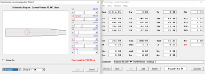
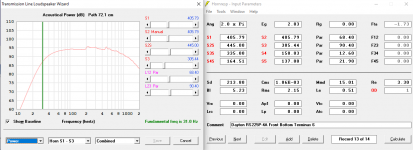
If you're asking me - what is the "stepped function"? Do you mean show the schematic? If so, here it is.
Double click on S1 on the input screen. All the S's will turn red to let you know you are in "stepped" mode.
Attachments
Okay, that makes sense, thanks. I offset one brace to 2/5ths of the width of the front panel, and the other to 1/3rd of the back panel.
Double click on S1 on the input screen. All the S's will turn red to let you know you are in "stepped" mode.
Okay, I see that - but I am still unclear what the stepped mode does?
Edit: this is with the braces accounted for in the sections.
Attachments
Last edited:
- Home
- Loudspeakers
- Full Range
- An Improved Transmission Line Alignment