I need to figure out what to do with the settings in the red rectangle.
Normally those are for sealed, BR, horns, so not required for [ML]TLs.
GM
If you make Apt the same diameter as Sd or big enough to mount the driver, then you can use Lpt to model a TL with just those 2 fields. Click on Fr until you get Apt and Lpt.
re post 103
I had a read over this in the weekend and tried it out first thing Monday at work where I have HR.
Wow, the best results ever from this programme. Thanks so much Patrick.
It actually worked just like you said it would! And didn't take much more time either.
So now I have a nice tapered design for my Dayton driver, RSS390HO, with an almost flat response from about 22Hz to around 150Hz.
I'm just not quite sure how to translate that into a transmission line enclosure like in post 104, the 'easy' one. I'm rather unfamiliar with HR; there may be a step I'm just not aware of.
Or like in the original one posted in number 98. That is, how do you use the horn response data (a tapered TL with offset driver) of a certain volume that I've calculated to get box dimensions with that 3:1 taper?
Moving right along, I've now settled on a HR sim that works well enough with the Dayton RSS390HO and am about to make sawdust, using Patrick Bateman's "Easy Way" drawing as a the basis for my simple-build TL subwoofer (post #104 above).
The only thing that puzzles me a little bit is that for the RSS390HO, a calculated vented box volume is 78L (Fb of 27.3Hz), and yet this TL that I'm about to build has a box volume of 145L and Fs of around 25.7Hz.
It sims fine enough I think and is flattish from about 25Hz to around 120Hz, but it worries me that in theory the TL box volume should be similar to that of the vented box.
I note that others with TLs using this driver have box volumes of around 150L so I may not be far off the mark.
Any comments would be appreciated.
Last edited:
I use the volume of a vented box for the same driver, as a bit of a "sanity check."
Basically, if your box volume is WAY more or WAY less than what the same sub needs, for a vented box, then something probably went wrong.
I use this 'rule of thumb' specifically because a lot of the videos on Youtube are based on ideas from the 80s and 90s, and those ideas are flat-out wrong.
In a nutshell, we weren't really able to model transmission lines until around 2004, when Martin King came out with a Mathcad model for transmission lines. But there were a lot of transmission lines built in the 80s and 90s, and those tlines were mostly a guess.
You can *definitely* make a tline larger than a vented box. The main challenge that you run into, is that when the box gets bigger and bigger, it starts to get peakier. Basically the resonant peaks in the transmission line start to become excessive.
Back in the 80s and 90s, a lot of tlines were filled with a LOT of stuffing. In many of those cases, the stuffing was mostly because the box was too big in the first place, and the stuffing was just attenuating the peaks.
But now in 2020, we can use Hornresp instead. And Hornresp gives us the opportunity to smooth out the response geometrically, instead of depending on the use of lots and lots of polyfill.
Thanks for that Patrick.
I seem to get an even smoother flatter response with light stuffing of the first and second segments, so might try both with and without stuffing once I've put it all together.
Many thanks for taking the time to explain this method for developing a TL subwoofer. Hopefully after the weekend or perhaps the next I can report back on how it compares with my original Pipeline sub (used 3.5m of storm water drain but with the driver at the end). That TL did great one note bass at around 20Hz, but was otherwise not so great, and looked a shock (according to my sig other who made nasty disparaging toilet bend jokes about it; I quite liked its other-worldy appearance). So it's nice to be doing the basic theory first and a build based on that. Much more sensible.
Im also wanting to try a simple TH at some point and I know there are some easy build designs for those too, but that project is for another time.
Last edited:
One other thing I should just ask.
Instead of the driver being mounted at the end of the box, I tried to sim using HR with the 15 inch driver (RSS390 HO) at the bottom of the long side of the enclosure, at the end of S1.
But I just could not seem to get a good result this way. Am I missing something? Or is it more likely that it works best with the driver at the end of the enclosure, right at the S1/S2 junction?
It was more a case of aesthetics than anything; it looks better with the driver facing out and the box standing up, rather than the box lying down and the driver facing out.
Otherwise, Im forced to have the driver downfiring when the box is upright - I have no real problem with that - or the driver upfiring with the vent, again, just not as good of a look as with the box upright and the driver facing outwards.
Cheers
P
Last edited:
You are offsetting the driver (Zd affects where the harmnics are. Usually one places the driver where the 1st unwanted harmonic is canceled meaning one can use less damping and get more bass.
dave
dave
Er, when the driver is at the end of the box, it is already offset (see image below) at the S1/S2 junction. The line starts at the other end of the enclosure so what I'm wanting to do is just move it back around the corner onto the long axis of the box. But I get seem to get a nasty spike when doing that, presumably the first harmonic.
I thought that there was a bit more leeway with where the driver could be placed in an offset situation, so long as it was roughly one-third of the way down the line.
I guess not.
I thought that there was a bit more leeway with where the driver could be placed in an offset situation, so long as it was roughly one-third of the way down the line.
I guess not.
Attachments
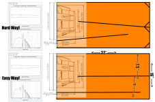
Not really. 'End of the box' is not a synonym for the throat of the line and it's the tap location relative to that that counts. Position at the throat provides maximum excitation to the fundamental and all relevant harmonics, adjusting the tap location of the drive unit affects the level of excitation of both, but in most situations the greatest significance being on the latter. There is a degree of latitude in position before significant differences occur, but how much depends on the line geometry and initial location.
Thx for that Scottmoose. Wont be changing position of driver anyway. Just wondering why the HR sim works well with driver in that position but not nearby. What you say makes sense.
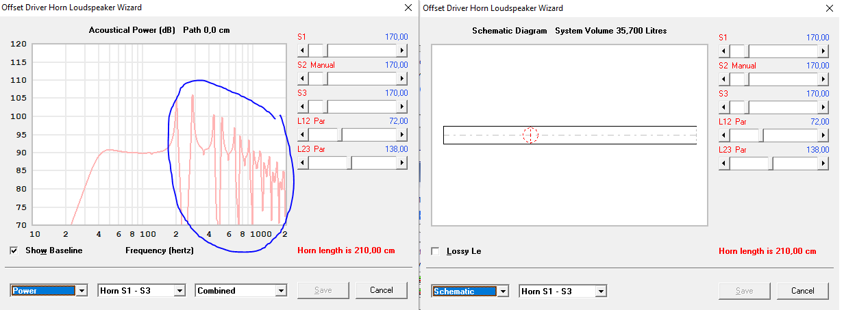
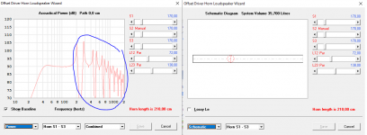
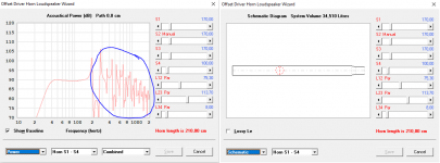
I'm looking at two versions of my TL design, one has an equal cross section (Sd) along the line while the other gets smaller near the end, so a smaller opening in the cabinet.
I can see that the power graph also takes on a different style or type of waves (circled in blue), but I have no clue if either one of them is favorable over the other. Does anyone have some insight in this?

I can see that the power graph also takes on a different style or type of waves (circled in blue), but I have no clue if either one of them is favorable over the other. Does anyone have some insight in this?
Attachments
I suggest you read Martin King's site & the several pdf files there if you wish to know more on the theory Transmission Line Theory
The very short version: the second provides a (very) minor amount of mass-loading which will reduce the level of the pipe harmonics a touch, and also lower the fundamental slightly.
The very short version: the second provides a (very) minor amount of mass-loading which will reduce the level of the pipe harmonics a touch, and also lower the fundamental slightly.
Playing around with the stuffing function in the loudspeaker wizard will do this too, ie, reduce the impact of the pipe harmonics.
Thx for that Scottmoose.
IOW, best overall is at an odd harmonic and 3rd is mostly the best overall of the others. 😉
GM
one has an equal cross section (Sd) along the line while the other...... a smaller opening in the cabinet.
Better to put a proper vent in the latter or taper from top to bottom if wanting a TL [aka TQWT].
GM
IOW, best overall is at an odd harmonic and 3rd is mostly the best overall of the others. 😉
GM
There he goes -saying in one sentence what I usually take a page of text to do. 😉
How're you doing over there Greg? Keeping safe I hope?
I started to post the 3rd harmonic was the best of the 'best', but decided it was a bit too cryptic. 😉
No Covid [yet]; working on a PM as 'speaking my mind' would likely get me banned.
GM
No Covid [yet]; working on a PM as 'speaking my mind' would likely get me banned.
GM
- Home
- Loudspeakers
- Full Range
- An Improved Transmission Line Alignment