Gotta click “though-hole” in search parameters.
https://www.digikey.com/en/products...oric-bc-components/NTCLE100E3472JB0A/12814211
https://www.digikey.com/en/products...oric-bc-components/NTCLE100E3472JB0A/12814211

Looks great! 😎
Please post it in the F5 Turbo thread -
https://www.diyaudio.com/community/threads/f5turbo-illustrated-build-guide.254056/
Please post it in the F5 Turbo thread -
https://www.diyaudio.com/community/threads/f5turbo-illustrated-build-guide.254056/
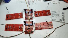
Well, I decided to walk on the wild side. I built a new board using 220ohm resisters for R5-1/2 W, R6- 1/2W, R7 - 3W, R8-3W, but my attempt to bias the board resulted in no movement on the bias or offset readings. I moved the pots throughout their range and got nada. The parts for Q1, Q2, Q3 and Q4 were sourced from a new F5 parts package from the DIY store. I'm using NTC 4.7K thermistors which are different from what I've used in the past NTCLE428E3472H400A.Change R5 R6 R7 R8 to 150 or 220 ohm. You will get more gain, at the expense of a bit of feedback. I built one F5 stock, one with 150ohm resistors, and they sound identical, but the one with 150R is noticeably more sensitive. People who have build them with 220R report wonderful sound and the ability to clip it with a CD player.
Appreciate suggestions....
Attachments
Well phooey.
I was obviously looking at the original F5 schematic when I rattled off those resistor positions.
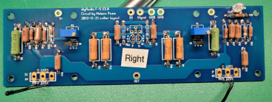
The feedback resistors, the 4 big ones in the middle that connect the amplifier output to the jfets, should be 220ohm.
The output mosfet source resistors, currently you have big green ones, need to be 0.47ohm.
I was obviously looking at the original F5 schematic when I rattled off those resistor positions.
The feedback resistors, the 4 big ones in the middle that connect the amplifier output to the jfets, should be 220ohm.
The output mosfet source resistors, currently you have big green ones, need to be 0.47ohm.
To be fair, that was a pretty old post which predated the V3 pcb. 🙂
Ok. Good to know. I will swap out the parts and report back.Well phooey.
I was obviously looking at the original F5 schematic when I rattled off those resistor positions.
The feedback resistors, the 4 big ones in the middle that connect the amplifier output to the jfets, should be 220ohm.
The output mosfet source resistors, currently you have big green ones, need to be 0.47ohm.
Yikes! Good catch. Not sure if this was a late at night screw up or just any moment of the day.
I will swap them out as well.
Thanks,
I will swap them out as well.
Thanks,
Please also check the colour banded resistors R1, R2, R5 and R6.
R1 and R2 appear the same in your photo but they are different in the schematics. (See https://firstwatt.com/pdf/art_f5_turbo.pdf page 2) Also please confirm R5 and R6 are 2.21K since the bands look like they may be 220R.
R1 and R2 appear the same in your photo but they are different in the schematics. (See https://firstwatt.com/pdf/art_f5_turbo.pdf page 2) Also please confirm R5 and R6 are 2.21K since the bands look like they may be 220R.
Dennis,
Thanks for catching R2. I have a bad habit of mixing up ohm vs. K values or, in this case, 4.75 vs 47.5.
I get new supply of 22.1K tomorrow and will instal them and go from there.
Thanks again,
Chip
Thanks for catching R2. I have a bad habit of mixing up ohm vs. K values or, in this case, 4.75 vs 47.5.
I get new supply of 22.1K tomorrow and will instal them and go from there.
Thanks again,
Chip
FLARRRRGGG
looking for some troubleshooting advice, please.
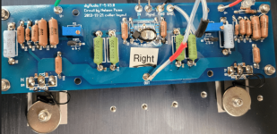
I built one stereo F5 successfully. Working on my second F5... got one channel up... was in the middle of booting up the other, when two of the multi meter leads touched each other. I think it was the one across R7. R7 and R8 were at roughly 400mA at the time.
R8 looks a little brown and R14 glowed and melted. And my heart got tossed in the gutter.
Is there any way to tell what else died? Like the transistors? Maybe a better way to phrase this is: I'm trying to figure out if i need to build another channel or if there is a way to salvage this one. How do I assess that?
looking for some troubleshooting advice, please.
I built one stereo F5 successfully. Working on my second F5... got one channel up... was in the middle of booting up the other, when two of the multi meter leads touched each other. I think it was the one across R7. R7 and R8 were at roughly 400mA at the time.
R8 looks a little brown and R14 glowed and melted. And my heart got tossed in the gutter.
Is there any way to tell what else died? Like the transistors? Maybe a better way to phrase this is: I'm trying to figure out if i need to build another channel or if there is a way to salvage this one. How do I assess that?
Thanks to all the help I have the correct resistors in place according to the F5 BOM. I put 220 ohm / 3 watt resistors in place at R9, R10, R11, R12 to experiment with the sound from the amp cards.
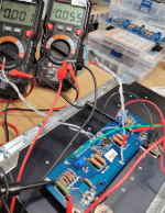
But the good old DBT has indicated that something is amiss.
Tested by itself, the PSU measure 23.42 +/-.
When I wire up the amp cardis when the Bulb burns brightly.
I've double checked all the resistors and Q1 thru Q6, and checked that Q3 and Q4 are in the right positions. As well as Q1 and Q2.
I've checked for a short at the Mosfets.
I'm missing something.
Attachments
Ok - so i had another 100 Ohm resister. I swapped out the melted R14 for the new one.FLARRRRGGG
looking for some troubleshooting advice, please.
I built one stereo F5 successfully. Working on my second F5... got one channel up... was in the middle of booting up the other, when two of the multi meter leads touched each other. I think it was the one across R7. R7 and R8 were at roughly 400mA at the time.
R8 looks a little brown and R14 glowed and melted. And my heart got tossed in the gutter.
Is there any way to tell what else died? Like the transistors? Maybe a better way to phrase this is: I'm trying to figure out if i need to build another channel or if there is a way to salvage this one. How do I assess that?
i turned down P1 and P2 so there was again 0 ohms across R5 & R6 .
I put the bulb tester back in - powered on. Bulb went dim.
I took the bulb tester out. Powered on and R14 fried instantly.
Does that imply Q4 is dead?
(sorry if answer is obvious... i can build stuff, but i'm not much of an EE)
- Home
- Amplifiers
- Pass Labs
- An illustrated guide to building an F5