Hello there,
With the amplifier circuit connected, and the Pots (variable resistors) set fully counter clockwise, and the power on, there is no/little load is on the PSU, the LEDs should be illuminated. For a correctly running configuration, if you turn the power off at this point then the PSU voltage will slowly decay over some minutes and the LEDs will gently fade, it seems this is what happened for your +ive voltage line but not the -ive.
I have had a situation once where I had a faulty Pot, the screw was turning and I could hear the reassuring click to indicate that it was set correctly, but the lever within the Pot was not actually moving, the Pot was instead stuck mid-resistance range, I confirmed this was the case by measuring the resistance of the pins of the Pot while turning the screw, the resistance was static measuring ~2KOhm. Other than that, one of your components were faulty, shorting or incorrectly placed.
I found a de-soldering iron and component tester useful in error sourcing. The amp does sound very nice once up and running correctly.
Regards

Btw, I am using NTC thermistors that are insulated within an epoxy resin, meaning the solder contacts at the head of the NTC are electrically insulated from the casing of the Mosfet.
Assuming the R5/R6 close to zero measurements were done correctly (eg, not on an incorrect range for a manual ranging meter), that should be ok as far as the initial setting of P1 and P2 are concerned. This can still be verified. In fact, you should still be able to measure R5/R6 while turning the corresponding pots to verify those parts are working correctly.
As other members have commented, shorting or incorrect parts placements are the likely issues.
Unfortunately there will some parts pulling/testing/replacing for this. 🙁
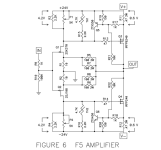
Can you check if that's a shadow on the R9/R10 (100R 3W) resistors or if there's some scorching. If that's thermal, you might consider changing them along with R3.
Since the power supply PCB is split, can you indicate which side is V+ and which is V-?
As other members have commented, shorting or incorrect parts placements are the likely issues.
Unfortunately there will some parts pulling/testing/replacing for this. 🙁
Can you check if that's a shadow on the R9/R10 (100R 3W) resistors or if there's some scorching. If that's thermal, you might consider changing them along with R3.
Since the power supply PCB is split, can you indicate which side is V+ and which is V-?
Hi folks. It appears that I have way too many projects in the queue (Aleph J, Aleph 60, Pearl 2 and a dual mono version of the Whammy) and while sorting through my boxes of bits and pieces during a recent house move I came across a set of boards for the F5 that I bought a few years ago from the store. Unfortunately I can't find the rest of the kit that I'm sure I bought at the time but if anyone is interested in these boards they are free to a good home (continental US).
Thanks,
Gary
Thanks,
Gary

If anyone is interested please PM me. First come first served 😊
Hello,
Built F5 few years ago using this guide. Thanks to 6L6.
I used the board by designed by Cviller.
Recently while testing a preamp with F5, left channel was damaged.
So ordered jFet from Diyaudio store. I replaced the jFets, transistors and Mosfets
The problem now is that I can only bias R11 up to only 0.020V.
R12 can bias up to 0.6V easily.
Having spent many hours reading this thread, I also increased the resistors R3 and R4 to 4.7K
but still no changes, cannot bias R11 to 0.6V.
Voltages across R3 and R4 are about 3.6V.
Now at a lost of what to do next.
When constructing, everything works the first time I power up. Joy.
Please help. Thanks
Is there a load attached? If yes, then look for DC offset at the output, If no, then we have a mystery in that
the current through the outputs should be equal.
the current through the outputs should be equal.
Work the bias pots until you get zero offset.
The bias pull against each other and need to be in balance… this balance is read as zero DC offset on the speaker output.
The bias pull against each other and need to be in balance… this balance is read as zero DC offset on the speaker output.
In order to achieve zero dc offset, R11 and R12 must be about 0.6V. But I am getting only 0.020V for R11. The Mosfets are not conducting, not warm.Work the bias pots until you get zero offset.
In the past, jfets were made by Linear Technology. No problems.
Q2 seems to be normal, that's why I get 0.6V at R12.
What next to try
In order to get zero offset, the voltage across R11 and R12 must be even. If they were both at 0.1V, the offset would be near or at zero. If they were both at 0.2v, the offset would be near or at zero.
Does any amount of turns, in either direction, on P1 get anything other than your measured 0.02v across R11?
Does any amount of turns, in either direction, on P1 get anything other than your measured 0.02v across R11?
Turn P1 to max only able to get 0.02V. Turn the other direction I get 0V. P2 very responsive small turn can change voltage at R12 easily.
Look at voltage at R1, it's high,
should be about 0.07V
Look at voltage at R1, it's high,
should be about 0.07V
3.6V across R3 is too low, should be about 4.2V. This is the voltage to the output mosfet gate and too low voltage will not turn on the mosfet.
0.2V across R1 is too high, too much current.
Perhaps Q5 is faulty and passing too much current, diverting current from R3/trimmer.
Try replacing Q5, or at least remove Q5 and test it.
0.2V across R1 is too high, too much current.
Perhaps Q5 is faulty and passing too much current, diverting current from R3/trimmer.
Try replacing Q5, or at least remove Q5 and test it.
Removed Q5 still the same .Try replacing Q5, or at least remove Q5 and test it.
Could the problem is from the
Jfets? They measured 7.8mA.
The old ones were 10mA.
On my schematic I wrote down 8 to 12mA Idss. But I can't remember is this a requirement.
Not sure what you did.
If you removed Q5 and powered up, did you try adjusting the trimmer and measure the voltage drop across R3?
I missed it earlier but voltage across R4 is also 3.6V? But voltage across12 is correct at 0.6V. That is strange.
Not sure what you did. Did you remove Q5 and tested Q5? Or did you remove Q5 and powered up?Removed Q5 still the same .
If you removed Q5 and powered up, did you try adjusting the trimmer and measure the voltage drop across R3?
I missed it earlier but voltage across R4 is also 3.6V? But voltage across12 is correct at 0.6V. That is strange.
- Home
- Amplifiers
- Pass Labs
- An illustrated guide to building an F5