I pulled these F5 V2.0 (2010) completed boards out of the drawer thinking I would sell them. I cleaned them up, checked all the solder joints, bolted them to heat sinks, and adjusted the bias. Everything works great...bias set at .6V with a couple mV of offset, but when I attached them to the spectrum analyzer I get this odd graph posted below. Is it me (set-up), or the amp?


Last edited:
...what's odd about it? 2nd harmonic 70db below the fundamental, PSU noise pretty quiet. What is your oscillator?
Mine seems odd because the graph in Nelson's article looks like this (3rd harmonic dominant):

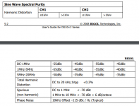
According to this the generator is “<0.2% THD”
https://beyondmeasure.rigoltech.com/acton/attachment/1579/f-001b/0/-/-/-/-/file.pdf
I suspect a lot of that measurement is the imprecision of the generator.
https://beyondmeasure.rigoltech.com/acton/attachment/1579/f-001b/0/-/-/-/-/file.pdf
I suspect a lot of that measurement is the imprecision of the generator.
Your distortion level looks high to me.
I snipped the attached section from the Rigol manual and the spec'ed THD limit of the sine wave isn't that low. Have you measured the generator's distortion at 1K output?
Can you try another generator?
Edit: Just saw Jim's post on the same point.
I snipped the attached section from the Rigol manual and the spec'ed THD limit of the sine wave isn't that low. Have you measured the generator's distortion at 1K output?
Can you try another generator?
Edit: Just saw Jim's post on the same point.
Attachments
I can...I have an Akitika 1 kHz Oscillator I will use next. In the mean time I blew a fuse in my Autoranger, which means trying to locate those little fuses amidst all my accumulated stuff. Wish me luck.Can you try another generator?
The generator is external, but I could try the internal REW generator...that a good idea too.Spectrum analyzer is from REW and generator comes from REW too, I suppose 🤔
Just a follow up...this is the best I can do measuring the Akitika Oscillator and then the F5 driven by the Akitika Oscillator:


How do your JFETs measure? You remember where they were sourced/how well they were matched? Haven’t built the F5 but if you can measure the current through them directly or indirectly you may find something. Though that may not make any sense since offset is zeroed. HmmJust a follow up...this is the best I can do measuring the Akitika Oscillator and then the F5 driven by the Akitika Oscillator:
View attachment 1114997View attachment 1114998
Edit: if the jfets have varying IDSS and or the associated resistors are off in value, you may have induced a P3 effect. Worth checking out

Last edited:
Looks like you’ve found out that the F5 is probably the most accurate amp in the Firstwatt series. It’s passing along your oscillator almost exactly, and doing very little editorializing in the higher harmonics.
Hi Kevin,
I'm surprised by your distortion (~0.012%) with just the akitika + autoranger. I found an older post ( https://www.diyaudio.com/community/threads/f5-power-amplifier.121228/page-823#post-6760893 ) where the akitika showed low distortion when you measured it with a Keithley 2015.
If you still have the Keithley, can you try using it to measure the F5?
Cheers,
Dennis
Can’t argue with that: but what about the 2nd order dominance?Looks like you’ve found out that the F5 is probably the most accurate amp in the Firstwatt series. It’s passing along your oscillator almost exactly, and doing very little editorializing in the higher harmonics.
The Akitika oscillator distortion looks high.
Akitika Oscillator
At the specified 2PMM, it should measure 0.000 002 of the signal, or 0.0002%. The webpage also stated the second harmonic was measured at 115dB below the fundamental.
A description (picture would be better) of the test setup and measurement procedure may help in troubleshooting.
Also the distortion graphs need their Y-axis adjusted to show the bottom end of the output.
Yes, I measure the Akitika with the Keithley 2015 simultaneously connected to the same breakout box as the Autoranger -> Focusrite. The THD doesn't even register since it is so low (as advertised). I'm measuring the Akitika at 450mV because that's what it takes to drive the F5 to 2.83V. I think that residual 2nd harmonic is coming from something down the chain (meaning the Autoranger or Focusrite), but that doesn't make sense.If you still have the Keithley, can you try using it to measure the F5?
A description (picture would be better) of the test setup and measurement procedure may help in troubleshooting.


F5 powered by Rigol DP832 Lab Supply, F5 is fed by Akitika oscillator, Output of F5 goes to 8 ohm dummy load, signal from dummy load connects to breakout box, Autoranger -> focusrite and Keithley connect to breakout box.
I suggest simplifying the arrangement - from dummy load to autoranger to Focusrite to computer.
Test both the amp board and oscillator with only the autoranger and Focusrite to computer.
Also test the oscillator direct to Focusrite as you can adjust the oscillator output so that you don't overload the Focusrite.
The Focusrite is supposed to be at its lowest distortion when its input level adjustment is at about 11 o'clock.
- Home
- Amplifiers
- Pass Labs
- An illustrated guide to building an F5