you can mount two equal resistors (P3/2) , or mount P3 and set it to measure equally across source resistors, or from mid to outer pins, before soldering in
Thanks for response all two, understod !! Cross fingers for set up the bias.... but tonight more. My wife is looking for me jajajaaj
Mount P3, set to mid point.
Sometime in the future when you have a way to measure distortion, you will be very, very pleased P3 is there.
Sometime in the future when you have a way to measure distortion, you will be very, very pleased P3 is there.
You have all reason, I'll go to the electronic shop for bough it, because I haven't !!!
Thanks again !!
Thanks again !!
F5 Bias adjust problem
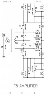
Hello all, Now I'm adjusting bias.... in the pcb F5 V3.0 I have to find the 0.4v initially in R7 with P1 and R8 with P2. I can find the 0.4v in P1 but PS start to increase current noise. When I'm adjusting P2 the voltage of R8 are 0 always.... Do you know what can happen ?
Hello all, Now I'm adjusting bias.... in the pcb F5 V3.0 I have to find the 0.4v initially in R7 with P1 and R8 with P2. I can find the 0.4v in P1 but PS start to increase current noise. When I'm adjusting P2 the voltage of R8 are 0 always.... Do you know what can happen ?
Attachments
Can you verify on the PCB that V+ and V- have the correct voltages (~+/-24V or so)?
Then measure the voltages across: R3, R4, R5 and R6.
Then measure the voltages across: R3, R4, R5 and R6.
Yes. Big problem.
Please contact the diyaudio store and I'm sure they will be able to sort this out.
Please contact the diyaudio store and I'm sure they will be able to sort this out.
Well, after some decorating, building a new rack (both pictured) and Christmas, and getting hold of some Mosfets (with an M2X) I put everything back together without mishap this time and have had it on test - very pleased so far but there is a miniscule amount of hum I need to track down. Thanks for all your help! 😀
View attachment 906147
I've been through my connections and connectors and not found any obvious hum reduction. With nothing connected to the input there's no hum, but as soon as I connect my source (Logitech Transporter, no dedicated Pre) I get the hum. Same with CD player swapped in instead.
Most of the time it's inaudible above the music but my wife often sits with head near one speaker plyaing low volume and it's definitely noticeable there.
Any thoughts on additional hum reduction? It's a by-the-book build with only difference a Velleman Speaker protect circuit on the outputs.
...With nothing connected to the input there's no hum, but as soon as I connect my source (Logitech Transporter, no dedicated Pre) I get the hum. Same with CD player swapped in instead.
Input ground loop. Can be tricky. Photos of everything please. 🙂
Hello all !!
I'm building F5 amp and after the first bias adjustment, in about 5 seconds I have to swich of because the R 11,12,18 and 19 are too hot..... and in the other chanel, the R13 is burned.... I'm not sure about why.... somebody can help me??
Thanks
I'm building F5 amp and after the first bias adjustment, in about 5 seconds I have to swich of because the R 11,12,18 and 19 are too hot..... and in the other chanel, the R13 is burned.... I'm not sure about why.... somebody can help me??
Thanks
Attachments

Input ground loop. Can be tricky. Photos of everything please. 🙂
Well I dismantled again ostensibly to get pics - removed the Velleman speaker protect module as I read there was no start up thump to worry about, and hey presto - hum has gone. 🙂
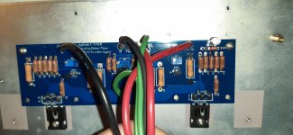
morenmgu - w/o seeing where all your wires go from the boards, It's tough to fully check.
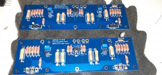
It looks like you've stuffed the boards correctly, but at least one other person should comment, and there were a few values I could not see.
Here are a few things I see.
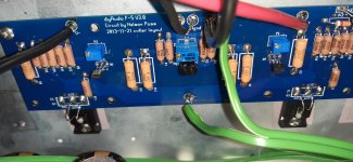
1) Board on left, you have a solder bridge shorting your input. This shouldn't cause your issue, but you'll need to clean that up.
2) I can't tell how you have your boards mounted. Do you have stand-offs separating the board from your heatsinks? If not, you may have some of your wiring shorted to the heatsinks, particularly if you stuffed and soldered the wiring from the top after you installed the boards. This may relate to your situation. Did you check continuity for all the pins on the MOSFETs to the heatsink prior to installing your other wiring? Did you use a dim bulb tester for initial power up?
3) Eventually, you'll want some fender washers and some type of split washer or belleville washer to ensure your MOSFETs remain in good contact after a number of thermal cycles and that the pressure on the MOSFET is more evenly spread. Likely not related, but it's a thought.
I'm sure others will have some helpful thoughts.
It looks like you've stuffed the boards correctly, but at least one other person should comment, and there were a few values I could not see.
Here are a few things I see.
1) Board on left, you have a solder bridge shorting your input. This shouldn't cause your issue, but you'll need to clean that up.
2) I can't tell how you have your boards mounted. Do you have stand-offs separating the board from your heatsinks? If not, you may have some of your wiring shorted to the heatsinks, particularly if you stuffed and soldered the wiring from the top after you installed the boards. This may relate to your situation. Did you check continuity for all the pins on the MOSFETs to the heatsink prior to installing your other wiring? Did you use a dim bulb tester for initial power up?
3) Eventually, you'll want some fender washers and some type of split washer or belleville washer to ensure your MOSFETs remain in good contact after a number of thermal cycles and that the pressure on the MOSFET is more evenly spread. Likely not related, but it's a thought.
I'm sure others will have some helpful thoughts.
Last edited:
I am the middle of building an F5. Power supply works perfectly with and without dim bulb tester and measures 25.9 V at both V+ and -25.9 V at V-.
I built the F5 amp boards but mistakenly switched the 240 and 9240 Mosfets. So when I turned the power on with one amp board connected the bulb didn't dim, no noise or smoke. Turned off fairly immediately. Looked for shorts. Connected again with same result. Then discovered there were two types of Mosfets so I switched them around but the same result. Turn on power with Dim Bulb connected and bulb doesn't dim and PSU LEDs don't light up. One other thing is that using the continuity test on a multimeter the middle pin of both Mosfets is continuous with chassis ground.
So my question is are the Mosfets fried and I need to replace them or could something else be going on? If there is any other part of the build that could cause a short I can't find it.
One other thing that might be odd is the connections for speaker out and ground on the board have continuity. But that is also true on the other amp board that I didn't install and haven't connected Mosfets to. So I'm assuming that is normal?
Thanks.
Transformer Humming F5
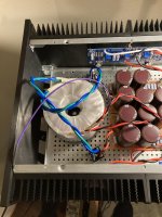
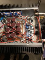
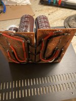
I finished my F5 build and it sounds great, except the transformer is humming (600VA antek). I feel like I have tried everything.
This 600VA hums when connected to mains and nothing connected to its secondaries. Thinking its a bad transfo and too large, I bought a new 300VA antek AS-3218 which doesn't hum with nothing connected to its secondaries. But when I wire it into the F5 amp, the 300VA transfo hums even louder than the previous one did. So loudly I can hear it with the lid on and it comes through the speakers woofer and tweeter from 5ft away.
Does this indicate a fault somewhere in my wiring/PSU?
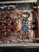
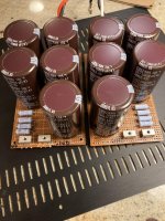
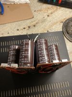
PSU has 15000uF x 5 per rail arranged CCRCCC
PSU rails: +-22.7VDC
I verified mosfets are NOT shorted to chassis and RCA inputs and speaker terminals not shorted to chassis either.
Only power earth is connected to chassis. PSU ground is not connected to chassis. I tried connecting PSU ground to chassis through CL-60 but the hum is still there.
If I connected just one amp board to the PSU, the trafo hums less loudly. If I connect 2 lm1875 boards to the PSU instead of the F5 boards, there is no hum at all...
I built the mains DC blocking circuit from Rod Elliott Mains DC and Transformers but it hasn't helped.
I swapped out both bridge rectifiers, but no change.
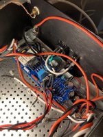
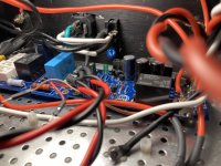
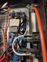
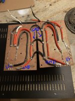
I have attached a lot of pics of my PSU since that is probably where the issue is. The black wire on the underside of the V+ board is ground and the red wire of the V- board is ground. The grounds are joined in 3 places as shown.
You can find a video that shows the humming here:
Antek 300VA humming buzzing on F5 power amplifier - YouTube
I appreciate any help at all!
I finished my F5 build and it sounds great, except the transformer is humming (600VA antek). I feel like I have tried everything.
This 600VA hums when connected to mains and nothing connected to its secondaries. Thinking its a bad transfo and too large, I bought a new 300VA antek AS-3218 which doesn't hum with nothing connected to its secondaries. But when I wire it into the F5 amp, the 300VA transfo hums even louder than the previous one did. So loudly I can hear it with the lid on and it comes through the speakers woofer and tweeter from 5ft away.
Does this indicate a fault somewhere in my wiring/PSU?
PSU has 15000uF x 5 per rail arranged CCRCCC
PSU rails: +-22.7VDC
I verified mosfets are NOT shorted to chassis and RCA inputs and speaker terminals not shorted to chassis either.
Only power earth is connected to chassis. PSU ground is not connected to chassis. I tried connecting PSU ground to chassis through CL-60 but the hum is still there.
If I connected just one amp board to the PSU, the trafo hums less loudly. If I connect 2 lm1875 boards to the PSU instead of the F5 boards, there is no hum at all...
I built the mains DC blocking circuit from Rod Elliott Mains DC and Transformers but it hasn't helped.
I swapped out both bridge rectifiers, but no change.
I have attached a lot of pics of my PSU since that is probably where the issue is. The black wire on the underside of the V+ board is ground and the red wire of the V- board is ground. The grounds are joined in 3 places as shown.
You can find a video that shows the humming here:
Antek 300VA humming buzzing on F5 power amplifier - YouTube
I appreciate any help at all!
Attachments
-
 IMG_8831.jpg680.2 KB · Views: 157
 -
 IMG_8832.jpg706.7 KB · Views: 156
 -
 IMG_8833.jpg740.2 KB · Views: 102
 -
 IMG_8839.jpg666.5 KB · Views: 120
 -
 IMG_8840.jpg715.4 KB · Views: 95
 -
 IMG_8841.jpg826.5 KB · Views: 108
 -
 IMG_8842.jpg579.7 KB · Views: 91
 -
 IMG_8836.jpg541.4 KB · Views: 90
 -
 IMG_8838.jpg674.4 KB · Views: 95
 -
 IMG_8834.jpg861.4 KB · Views: 110
Last edited:
I am the middle of building an F5. Power supply works perfectly with and without dim bulb tester and measures 25.9 V at both V+ and -25.9 V at V-.
I built the F5 amp boards but mistakenly switched the 240 and 9240 Mosfets. So when I turned the power on with one amp board connected the bulb didn't dim, no noise or smoke. Turned off fairly immediately. Looked for shorts. Connected again with same result. Then discovered there were two types of Mosfets so I switched them around but the same result. Turn on power with Dim Bulb connected and bulb doesn't dim and PSU LEDs don't light up. One other thing is that using the continuity test on a multimeter the middle pin of both Mosfets is continuous with chassis ground.
So my question is are the Mosfets fried and I need to replace them or could something else be going on? If there is any other part of the build that could cause a short I can't find it.
One other thing that might be odd is the connections for speaker out and ground on the board have continuity. But that is also true on the other amp board that I didn't install and haven't connected Mosfets to. So I'm assuming that is normal?
Thanks.
Get a cheap "component tester" from Amazon or eeebay and check the mosfets if you want to be sure
https://www.amazon.com/KKmoon-MRH16...ywords=Component+Tester&qid=1618368681&sr=8-5
Output- and GND are expected to be connected so don't worry about that
- Home
- Amplifiers
- Pass Labs
- An illustrated guide to building an F5