Thanks for the reply, Turion.
Not that it would affect the adjustment process but my "H2 Preamp V1 R0 (2019)" board requires a 24V power supply.
Is there another version of the H2?
Not that it would affect the adjustment process but my "H2 Preamp V1 R0 (2019)" board requires a 24V power supply.
Is there another version of the H2?
You’re right, my error. I just looked at Nelson’s notes on the original version…24V.
Yes, Nelson decided to update the board….see the latter parts of this forum:
H2
and this newer forum:
H2 V2 BUILD
The new board only needs 12V. Unfortunately, the original distribution of the new version is over but Nelson said they would be made available in the diyAudio store in the near future.
Cheers
This probably excludes the connection to the steel chassis of the housing?
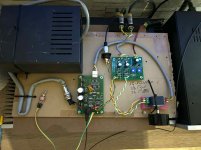
The mounting holes connected to circuit ground is meant for the circuit to connect to chassis and safety ground, so metal standoffs should be used and be sure to have good conductivity between the standoff and chassis.

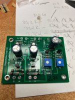
If you increase the value of R13 and R16, that will increase the voltage at T2. You can replace the existing 3.32k resistor with a higher value such as 3.6k. The exact value is not critical. Or if you have a couple of small value resistors (150R to 300R) handy, lift one leg of each of the R13 and R16 and series connect one resistor to each of R13 and R16.
But before you make any resistor changes are you measuring at the correct "T2"? There are two T2 at R8 and only the T2 on the right of R8 is the correct one.
But before you make any resistor changes are you measuring at the correct "T2"? There are two T2 at R8 and only the T2 on the right of R8 is the correct one.
Last edited:
According to the documentation, to achieve zero, I should have more than 17V in T2 points.
I am not sure what "to achieve zero" means. Where is this mentioned?
- Home
- Amplifiers
- Pass Labs
- An H2 Build Walkthrough