I thought I would add pictures into this thread - nowhere near as insightful as the build walk through but as I took a slightly different approach, I thought I would share.
I opted to build one that might be good for a local tour ( and shipped it out this am to its first experimenter)
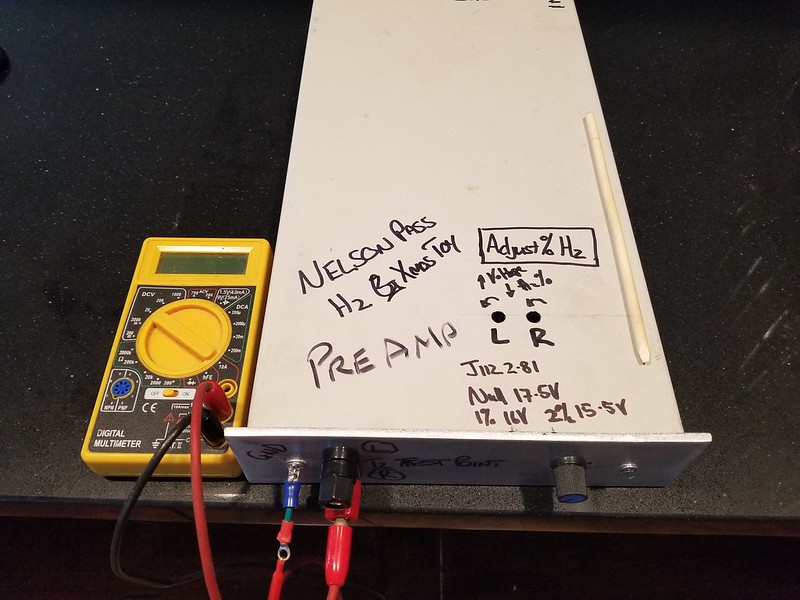
I installed the H2 into an old CD ROM case ( the same one I used to test the Korg B1 ) with an SMPS that is regulated to 24V, added an additional filter for good measure and a small pot to allow for volume adjustment ( so that it can be used as a preamp ).
I have added test points on the front and drilled holes aligned with the trim pots to allow the T2 voltage to be adjusted without opening the chassis. I couldn't find my nylon flat screwdriver so I shaped a tool out of a trusty bamboo chopstick which works very well.
Not pretty but functional and should be fool proof enough to allow most people to try this out.
and finally a picture of it at my desk ( the B1 Korg is below the stack )
It was a lot of fun to play with the amount of H2 and I do plan on doing more extended experimentation when I finally get it back again.
Thanks NP for another fun distraction.
..dB


Where in the signal chain are you putting the H2 device? After source or after pre? I see you state you added a volume control. Thanks.
Russellc
ItsAllInMyHead, I don't see you adding volume control so I assume you used it as I am suggesting? Oh, and thanks for your guide!
Correct. No attenuation. I am only using it between pre-amp and amp or between source and HP amp for the time being. Since I don't intend to use it as an HP amp or dedicated pre-amp and only between components, I had briefly inquired re: whether it would be wise to move to unity gain (per the article), but @6L6 mentioned that may change the 2nd harmonic character. So, I left it at the 14dB. The "problem" is that I don't need gain. So, I may yet try it at unity and see how things go.
@6L6 and the group -
Thanks as always. I had seen the videos (and was lucky enough to see the presentation live). Where I admit I get confused is ...
I understand at ~47:16 where Nelson begins to talk about the distortion % vs. output voltage. Clear to me. It seems the percentage of distortion is directly proportional to the output voltage (not the gain).
I also understand the slide beginning at ~48:00 showing the the frequency response vs. the gain.
I saw nothing in the presentation that notes a change in the character of the distortion other than the operation point settings. For further discussion, let's assume I set and leave those at the "1% at 0.5V" output settings. Again, if I understand it properly...
When I say "I understand" I should be careful... 😀
My follow up question is that as long as the H2 device is outputting the the same voltage to my amp => therefore the same listening level. Why does it matter where the system gain comes from?
I would vastly prefer to not add 14dB of gain into the system (that requires further attenuation) as long as I don't muck up the experiment.
I am wondering why 0.5V in from my pre-amp to the H2 at unity => 0.5V out would have a different harmonic character than 0.1V in from my pre-amp and out at 0.5V with 14dB gain (roughly 5x if I did my math correctly). I'm still learning.
If it does have a differing characteristic that I should be aware of, I'd love to learn more. Mainly... since I don't want particularly to use the device as a pre-amp or add another attenuator - I'd like to have unity gain while still preserving the H2 character. I am lost as to why if the voltage out of the H2 into the amplifier is the same - why the gain matters.
Thanks in advance for any insight!
Yes, very good question. I can see the value of adding a volume control and using as a preamp when wanting to see how it affects power amps. Just wondering how everyone is using it and how they are putting it in the chain.
Russellc
Russellc
Had my H2 hooked up between my phone and one of my headphone amps while putting together my summary. Stevie Ray Vaughan sounded just incredible. What's "fun" is that I still have the absolute phase inverted AND I'm getting positive H2 (if I understood the article properly). So, more play time ahead to tweak, compare, try with loudspeakers, and just generally have a blast playing with "Big Boy Toyz".
OH!!!!! Lest I forget. It calls this out in the article. DO NOT... I mean DO NOT get your power supply polarity backwards. You WILL release the magic smoke. Ask me how I know. 😱 😱 I guess now, I'm initiated.
😀
Your bolded statement above is and/or maybe the simplest and efficient practice for higher power applications.
Here is my understanding of your system as described above;
1 The stereo headphone output on the smart phone is the music source. Its output level is adjustable.
2. The output of the phone drives H2 as supplied [5X gain]. Its outputs must be adjusted to a level up to say; 0.5 Vrms.
3. The 0.5 Vout rms outputs of H2 drive the stereo headphone amp [HPA]. I am guessing that [HPA] has an input volume control to attenuate the level of the H2 output.
4. What is the Vp-p across each phone which your ears/headphones need? My Grado headphones/ears are satisfied with less than 100 mVp-p across each phone.
The above suggest that a dual volume control like the one [I guessed] in your [HPA] maybe inserted between H2 and the higher power amp. And, the use of the preamp in your higher power system may be not needed.
Best
Anton
Last edited:
Your bolded statement above is and/or maybe the simplest and efficient practice for higher power applications.
Here is my understanding of your system as described above;
1 The stereo headphone output on the smart phone is the music source. Its output level is adjustable.
2. The output of the phone drives H2 as supplied [5X gain]. Its outputs must be adjusted to a level up to say; 0.5 Vrms.
3. The 0.5 Vout rms outputs of H2 drive the stereo headphone amp [HPA]. I am guessing that [HPA] has an input volume control to attenuate the level of the H2 output.
4. What is the Vp-p across each phone which your ears/headphones need? My Grado headphones/ears are satisfied with less than 100 mVp-p across each phone.
The above suggest that a dual volume control like the one [I guessed] in your [HPA] maybe inserted between H2 and the higher power amp. And, the use of the preamp in your higher power system may be not needed.
Best
Anton
Anton - thank you for the kind reply. Apologies for any confusion. I'm not sure if your follow-up was related to my question from post #24. The post you quoted was with regard to my initial check to see if the H2 worked in general, and I happened to just leave it in the chain while I was typing up my initial posts.
I will not be using it in that configuration for longer-term listening most likely. That is primarily b/c I don't want to re-wire my HPs to get the "correct" phase. At this point, I am not sure I know of a way to get the correct absolute phase and the negative H2 with headphones without rewiring them or building an adapter. However, if anyone has a suggestion, I'm all ears. 😀
For my listening tests I was planning to primarily use loudspeakers. My preference would be to not have the additional 14dB of gain from the H2. @6L6 had mentioned to me in a separate conversation (and then again above he had inferred) that the gain affects the H2 character if I understood him correctly.
I am simply wondering why, and if so to what extent. In short, as long as the output voltage is "the same" I am not understanding the impact that gain would have. I know Nelson discusses gain, I was there. I simply am admitting that I don't understand. 😕
Put more simply, my question to the group was: Would one expect the same H2 character and general behavior from A and B below?
A - Input 0.1V => Output ~0.5V (If my math is correct re: 14dB gain)
B - Input 0.5V => Output 0.5V (Unity gain)
My original assumption was yes, but I seem to be incorrect and/or misinterpreting Nelson's article and presentation. I also wouldn't remove the possibility that I'm simply asking "the wrong question" 😀
Last edited:
Anton - thank you for the kind reply. Apologies for any confusion. I'm not sure if your follow-up was related to my question from post #24. The post you quoted was with regard to my initial check to see if the H2 worked in general, and I happened to just leave it in the chain while I was typing up my initial posts.
I will not be using it in that configuration for longer-term listening most likely. That is primarily b/c I don't want to re-wire my HPs to get the "correct" phase. At this point, I am not sure I know of a way to get the correct absolute phase and the negative H2 with headphones without rewiring them or building an adapter. However, if anyone has a suggestion, I'm all ears. 😀
For my listening tests I was planning to primarily use loudspeakers. My preference would be to not have the additional 14dB of gain from the H2. @6L6 had mentioned to me in a separate conversation (and then again above he had inferred) that the gain affects the H2 character if I understood him correctly.
I am simply wondering why, and if so to what extent. In short, as long as the output voltage is "the same" I am not understanding the impact that gain would have. I know Nelson discusses gain, I was there. I simply am admitting that I don't understand. 😕
Put more simply, my question to the group was: Would one expect the same H2 character and general behavior from A and B below?
A - Input 0.1V => Output ~0.5V (If my math is correct re: 14dB gain)
B - Input 0.5V => Output 0.5V (Unity gain)
My original assumption was yes, but I seem to be incorrect and/or misinterpreting Nelson's article and presentation. I also wouldn't remove the possibility that I'm simply asking "the wrong question" 😀
Hello ItsAllInMyHead,
Thanks for your post. Please visit the Articles Forum and find the one which is entitled "What is Gain Structure?" It discusses the management of signal levels in an audio system.
Your earlier Phone/H2/HPA setup may help test and resolve the two conditions in your bolded statement above; because H2 negative phase [H2np] has a characteristic sound. I speculate that [H2np] will be the same in both situations A or B.
Best
Anton
Last edited:
Hi Anton -
I read that article some time ago, thank you. I wonder its relevance to this conversation. In part, many of the reasons stated in that article are precisely why I'd prefer unity gain vs. 14dB. Have I shown a lack of understanding re:gain itself? If so, please advise. I'm always eager to learn. You clearly pointed me to the article for a reason, and 6L6 pointed me to the video for a reason. I had seen both, but when two intelligent people point me toward resources I feel familiar with already... I take note and wonder what I've missed.
Sadly, my phone / H2 / HPA setup will not help resolve my query. Simply because as previously stated it would be inverted absolute phase and providing positive H2 (unless I rewire them). Yes, ultimately my ears will be the judge, but at this point I am interested in the circuit's function.
Apologies yet again for not being clear. My query was not "Will they sound the same?". My query is more along the lines of "Would the signal output be identical"?
Thank you for providing your thoughts. I was told (or I believe I was) that the gain effects the H2 in some way that is entirely unclear to me. I have not found any evidence of that being the case.
Rather than derail the conversation further - I'll reach out to @6L6. It is likely I've misunderstood him or I've clearly missed the mark on something.
Once again, thank you for taking the time.
Best,
Patrick
Why not buy 2 cheap headphone jacks and make an adapter ?
Concerning the "other" question I am as perturbed as you are, I was planning to use the H2 as buffer, but I am unsure if the input voltage would than be limited to the equivalent of 1V OUTPUT - 14db ....
Maybe ask in the main thread ?
Max
Concerning the "other" question I am as perturbed as you are, I was planning to use the H2 as buffer, but I am unsure if the input voltage would than be limited to the equivalent of 1V OUTPUT - 14db ....
Maybe ask in the main thread ?
Max
@coolnose - That's a definite option. I had mentioned the possibility of an adapter earlier, but I debated whether that would be proper. I don't see why not.
Based on Nelson's graphs (in the video) at ~47:50 or in the article on page 7, he shows around 10% distortion at 2V, 2% at 1V and about 0.8% at 0.5V.
You're not limited to the 1V output, but the distortion is directly proportional to the output voltage. So, my general plan was a few little trials...
Attenuate the signal both before and after the H2 to see how I like it or if I can notice a difference.
A - Source => H2 => Pre-amp => Amp => Speakers
B - Source => Pre-amp => H2 => Amp => Speakers
Then, I may add a pot and go back to 14dB gain and simply do
Source => H2 => Amp => Speakers
Great suggestion. I think I'll pop back on the main thread. I think it's better to have the bigger conversations all in one place. Also, I've seen Nelson's posts, and who better to possibly answer my question than Nelson himself if he happens to catch it.
Last edited:
Put more simply, my question to the group was: Would one expect the same H2 character and general behavior from A and B below?
A - Input 0.1V => Output ~0.5V (If my math is correct re: 14dB gain)
B - Input 0.5V => Output 0.5V (Unity gain)
My original assumption was yes, but I seem to be incorrect and/or misinterpreting Nelson's article and presentation. I also wouldn't remove the possibility that I'm simply asking "the wrong question" 😀[/QUOTE]
Hi ItsAllInMyHead,
I read a possible misunderstanding in your bolded statements above.
1. The FET does not work as a unity gain device in option B. It still has a gain of 5X like in case A.
2. But; the 0.5 V input of case B must be attenuated first by a factor of 5. And the resultant 0.1 V at the gate of the FET is re-amplified by a 5X gain factor [by the same FET] to give a 0.5 V output at its drain.
3. It follows that the operation of the FET is the same in cases A and/or B and so is the magnitude of its resultant H2s.
Best
Anton
@coolnose - That's a definite option. I had mentioned the possibility of an adapter earlier, but I debated whether that would be proper. I don't see why not.
Based on Nelson's graphs (in the video) at ~47:50 or in the article on page 7, he shows around 10% distortion at 2V, 2% at 1V and about 0.8% at 0.5V.
You're not limited to the 1V output, but the distortion is directly proportional to the output voltage. So, my general plan was a few little trials...
Attenuate the signal both before and after the H2 to see how I like it or if I can notice a difference.
A - Source => H2 => Pre-amp => Amp => Speakers
B - Source => Pre-amp => H2 => Amp => Speakers
Then, I may add a pot and go back to 14dB gain and simply do
Source => H2 => Amp => Speakers
Great suggestion. I think I'll pop back on the main thread. I think it's better to have the bigger conversations all in one place. Also, I've seen Nelson's posts, and who better to possibly answer my question than Nelson himself if he happens to catch it.
I like the bolded option the best; because it is the simplest [no preamp]. It also works as I reported in my last post in the main H2 thread.
Best
Anton
Hi Anton -
I appreciate your patience. If I am understanding you correctly...
I understand 1 and 2 and had understood that prior. I apologize once again if I was unclear. All of that is confirming my original thought. The attenuation can be altered by resistors R1 and R2 based on my understanding of the article. That has been my understanding all along. If that's incorrect, someone chime in.
Per #3 it seems that the H2 character is independent of the "overall" gain from in to out. That follows my original understanding. I'll be swapping mine over to unity gain.
That's all I was trying to get at. I am happy that my original understanding and knowledge of the bits of how this actually works have been confirmed.
WHEW!
With thanks!
Make sure you orient the FETs the right way. These are the J112s. Check your parts. No, you can't just turn them around and put them on the other pads.
View attachment 800234
Make sure the regulators go in properly also. These are the LM317s. Check your parts.
View attachment 800237
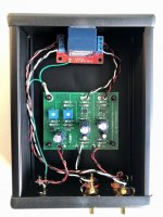
Fully stuffed board. Time to set the operating point. Make sure you have Papa's article.
View attachment 800240
Draw a vertical line on the graph corresponding to the values on your bag. It will intersect the curves at the various distortion levels Papa was kind enough to provide. Measure the corresponding voltage at T2 for each channel as noted in the article. Turn the pots per the article to match your voltage. Mine for 2.66 was about 15V1 to start at 1%
View attachment 800241
I wrote mine on the bottom for future reference.
View attachment 800242
Add some I/Os and you're good to go! I'll find a case for this soon.
View attachment 800243
Thanks once again to the ever-generous Papa and 6L6 for providing and coordinating an amazing project.
Much appreciated by this newbie DIYer, IAIMH!
Nelson provided guidance for additional filtering for the Original H2 in POST #477 of the H2 thread...
<https://www.diyaudio.com/forums/pass-labs/327746-h2-post6029944.html>
Would the RC recommendations be relevant to the Revised H2 design...or is the additional filtration already incorporated?
Perhaps Nelson could comment!?
My pleasure, Big Guy. I'm thrilled to see that people are still building and experimenting.
I can't answer your question directly with 100% confidence. I'll give it a try though based on memory and some knowledge of the sequence.
The tl:dr version if that if you have the "2019" boards - then you already have the lower noise version, I believe. His post was directed at those folks that had an earlier set of boards to instruct them how they might go about updating it for similar performance, I believe.
Yes, Papa or one of the other folks more familiar with this circuit could/should chime in for confirmation.
Enjoy playing / experimenting with it. It's addictive.
Adjusting P1 and P2
Hopefully people are still watching this thread.?!
Finally finished building the Revised H2 board into a build box but have a question on adjusting the voltage at the the Right and Left test points T2.
If I am planning to use the H2 in a path as follows
SOURCE > PREAMP > H2 > AMPS
does the full system need to be powered up and playing to make the adjustment?
My inexperienced gut says YES, but would appreciate a sanity check.
Thanks in advance.
Big Guy: I just finished building the H2 ver2 (H2V2) and put it into the same sequence of components as you (since I put it after a preamp I made it unity gain). For my board, it does not have to have the whole system powered up to make adjustments. Just plug in the 12V power source , let it sit for a bit then make your adjustments. Let it sit for awhile to monitor if there’s any drift.
I still check mine while it was running in the whole system anyway just to convince myself everything was good.
Cheers!
I still check mine while it was running in the whole system anyway just to convince myself everything was good.
Cheers!
Hopefully people are still watching this thread.?!
Finally finished building the Revised H2 board into a build box but have a question on adjusting the voltage at the the Right and Left test points T2.
If I am planning to use the H2 in a path as follows
SOURCE > PREAMP > H2 > AMPS
does the full system need to be powered up and playing to make the adjustment?
My inexperienced gut says YES, but would appreciate a sanity check.
Thanks in advance.
- Home
- Amplifiers
- Pass Labs
- An H2 Build Walkthrough