I was extremely fortunate to get a hold of an H2 kit. As a newb/noob/putz, I am learning a bit of the theory around what might make things “sound good” TO ME. I am fortunate to not have an opinion one way or the other. I love my measurement gurus that chase out every last bit of distortion, and I love my vinyl, tube, and secret sauce junkies. This is a hobby for me, so I learn as I go. So far it has been a blast.
Since there really isn’t a “build guide” so to speak for this, and there are few things I ran across that might trip up a few people – I thought I’d post some pictures of my build. If other relative newcomers got a hold of one, it may help. For others, it may just give you a chuckle.
This is not a substitute for Nelson's article or the primary thread on the subject.
Here’s all the goodies.

Here's "THE" bag. Per the article, pay special attention to the number on the bag. Write it down and/or don't lose the bag! You need this number! Also, make sure you have good enough glasses to read the part numbers. The parts look pretty similar in the bag. They're not. Two of the FETs and two of the regulators.

Here's all the parts laid out. You will need a 24VDC PSU, some I/O jacks, and a case also.

The board is really well laid out for ease of soldering with plenty of space between pads to avoid bridges. Also, most parts are mirrored for each channel.

I am new to a lot of this, so I label all of my resistors after measuring each of them with the DMM. Everyone has their own "tricks" or favorite ways. I haven't mis-stuffed a board yet... knock wood.

Keep a copy of the schematic at hand...

I stuff from small to large and tick off everything on the schematic as I go. Of course, I say that... and just noticed that I did not tick of the pots


To be continued...
Since there really isn’t a “build guide” so to speak for this, and there are few things I ran across that might trip up a few people – I thought I’d post some pictures of my build. If other relative newcomers got a hold of one, it may help. For others, it may just give you a chuckle.
This is not a substitute for Nelson's article or the primary thread on the subject.
Here’s all the goodies.
Here's "THE" bag. Per the article, pay special attention to the number on the bag. Write it down and/or don't lose the bag! You need this number! Also, make sure you have good enough glasses to read the part numbers. The parts look pretty similar in the bag. They're not. Two of the FETs and two of the regulators.
Here's all the parts laid out. You will need a 24VDC PSU, some I/O jacks, and a case also.
The board is really well laid out for ease of soldering with plenty of space between pads to avoid bridges. Also, most parts are mirrored for each channel.
I am new to a lot of this, so I label all of my resistors after measuring each of them with the DMM. Everyone has their own "tricks" or favorite ways. I haven't mis-stuffed a board yet... knock wood.
Keep a copy of the schematic at hand...
I stuff from small to large and tick off everything on the schematic as I go. Of course, I say that... and just noticed that I did not tick of the pots
To be continued...
Continued....
Make sure you orient the FETs the right way. These are the J112s. Check your parts. No, you can't just turn them around and put them on the other pads.

Make sure the regulators go in properly also. These are the LM317s. Check your parts.

Fully stuffed board. Time to set the operating point. Make sure you have Papa's article.

Draw a vertical line on the graph corresponding to the values on your bag. It will intersect the curves at the various distortion levels Papa was kind enough to provide. Measure the corresponding voltage at T2 for each channel as noted in the article. Turn the pots per the article to match your voltage. Mine for 2.66 was about 15V1 to start at 1%

I wrote mine on the bottom for future reference.

Add some I/Os and you're good to go! I'll find a case for this soon.

Thanks once again to the ever-generous Papa and 6L6 for providing and coordinating an amazing project.
Make sure you orient the FETs the right way. These are the J112s. Check your parts. No, you can't just turn them around and put them on the other pads.
Make sure the regulators go in properly also. These are the LM317s. Check your parts.
Fully stuffed board. Time to set the operating point. Make sure you have Papa's article.
Draw a vertical line on the graph corresponding to the values on your bag. It will intersect the curves at the various distortion levels Papa was kind enough to provide. Measure the corresponding voltage at T2 for each channel as noted in the article. Turn the pots per the article to match your voltage. Mine for 2.66 was about 15V1 to start at 1%
I wrote mine on the bottom for future reference.
Add some I/Os and you're good to go! I'll find a case for this soon.
Thanks once again to the ever-generous Papa and 6L6 for providing and coordinating an amazing project.
Last edited:
One more for good measure...
Had my H2 hooked up between my phone and one of my headphone amps while putting together my summary. Stevie Ray Vaughan sounded just incredible. What's "fun" is that I still have the absolute phase inverted AND I'm getting positive H2 (if I understood the article properly). So, more play time ahead to tweak, compare, try with loudspeakers, and just generally have a blast playing with "Big Boy Toyz".
OH!!!!! Lest I forget. It calls this out in the article. DO NOT... I mean DO NOT get your power supply polarity backwards. You WILL release the magic smoke. Ask me how I know. 😱 😱 I guess now, I'm initiated.
 😀
😀
Had my H2 hooked up between my phone and one of my headphone amps while putting together my summary. Stevie Ray Vaughan sounded just incredible. What's "fun" is that I still have the absolute phase inverted AND I'm getting positive H2 (if I understood the article properly). So, more play time ahead to tweak, compare, try with loudspeakers, and just generally have a blast playing with "Big Boy Toyz".
OH!!!!! Lest I forget. It calls this out in the article. DO NOT... I mean DO NOT get your power supply polarity backwards. You WILL release the magic smoke. Ask me how I know. 😱 😱 I guess now, I'm initiated.
😀
Last edited:
Very good initiative, just get the jfets straight 😉
Single transistors are obviously the jfets as they have been matched, the 2 on the strip are the regulators.
Following and looking forward to link to this walktrough
EDIT: Sorry I interfered while you where building the thread....
Single transistors are obviously the jfets as they have been matched, the 2 on the strip are the regulators.
Following and looking forward to link to this walktrough
EDIT: Sorry I interfered while you where building the thread....
Last edited:
@coolnose - Not a worry! I'm just happy someone found it. I had to type quickly to get in under the edit time.
@grimberg.... oh... he knows 
At BAF, he mentioned that posts with tons of pictures were helpful... so this was my attempt.
6L6 actually has skills to answer questions. 😀 Thus, his are build guides. I'm just off training wheels, and I can hardly guide myself.
This was just fun.
At BAF, he mentioned that posts with tons of pictures were helpful... so this was my attempt.
6L6 actually has skills to answer questions. 😀 Thus, his are build guides. I'm just off training wheels, and I can hardly guide myself.
This was just fun.
Are you kidding???? It’s awesome!!Publishing build guides is 6L6's thing. Wait until he finds out. You should brace yourself.
Absolutely fantastic, I’m super glad somebody stepped in and did this! Thank you Mr. I.A.I.M. Head!
😀 😀 😀
I thought I would add pictures into this thread - nowhere near as insightful as the build walk through but as I took a slightly different approach, I thought I would share.
I opted to build one that might be good for a local tour ( and shipped it out this am to its first experimenter)
I installed the H2 into an old CD ROM case ( the same one I used to test the Korg B1 ) with an SMPS that is regulated to 24V, added an additional filter for good measure and a small pot to allow for volume adjustment ( so that it can be used as a preamp ).
I have added test points on the front and drilled holes aligned with the trim pots to allow the T2 voltage to be adjusted without opening the chassis. I couldn't find my nylon flat screwdriver so I shaped a tool out of a trusty bamboo chopstick which works very well.
Not pretty but functional and should be fool proof enough to allow most people to try this out.
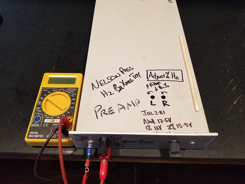


and finally a picture of it at my desk ( the B1 Korg is below the stack )

It was a lot of fun to play with the amount of H2 and I do plan on doing more extended experimentation when I finally get it back again.
Thanks NP for another fun distraction.
..dB
I opted to build one that might be good for a local tour ( and shipped it out this am to its first experimenter)
I installed the H2 into an old CD ROM case ( the same one I used to test the Korg B1 ) with an SMPS that is regulated to 24V, added an additional filter for good measure and a small pot to allow for volume adjustment ( so that it can be used as a preamp ).
I have added test points on the front and drilled holes aligned with the trim pots to allow the T2 voltage to be adjusted without opening the chassis. I couldn't find my nylon flat screwdriver so I shaped a tool out of a trusty bamboo chopstick which works very well.
Not pretty but functional and should be fool proof enough to allow most people to try this out.
and finally a picture of it at my desk ( the B1 Korg is below the stack )
It was a lot of fun to play with the amount of H2 and I do plan on doing more extended experimentation when I finally get it back again.
Thanks NP for another fun distraction.
..dB

Looking forward to building this. Hopefully it comes in the mail tomorrow. The post office in my area can be slow
I have added test points on the front and drilled holes aligned with the trim pots to allow the T2 voltage to be adjusted without opening the chassis. I couldn't find my nylon flat screwdriver so I shaped a tool out of a trusty bamboo chopstick which works very well.
Not pretty but functional and should be fool proof enough to allow most people to try this out.
Great implementation of the H2 board with the test points and easy access to the H2 adjustment pots.

The icing on the cake would be a copy of the calibration curves on the cover of the case. 🙂
Edit:
I thought the vertical line on the calibration graph was for the calibration of your H2, but it is different from the voltages written on the top of the case.
Last edited:
You are right about the graph, I copied it from the build thread merely as a representation of the curve. My Vp is 2.81v
About to start on my kit, (Thanks 6l6 and Nelson) and have a question or two. Reading the article, it appears this unit has some gain. I read where it can be lowered to unity if desired with appropriate parts substitutions.
1. What gain is it as supplied?
2. Are folks adding a volume control, I wanted to just insert it in signal path (I assume between pre and power amp) or am I missing the boat here, or need to convert to unity gain?
I've read where a member used it with HP amp and headphones, I intend to use in pre-power-speaker chain. ItsAllInMyHead, I don't see you adding volume control so I assume you used it as I am suggesting? Oh, and thanks for your guide!
Thanks
Russellc
Last edited:
As I understood, a voltage divider just lowers the input signal in order to make it 'unity gain'. Nelson's article tells you about the original gain and the values of input resistor pair for gain of one. Don't remember unfortunately.
Cheers, Ernst
Cheers, Ernst
- Home
- Amplifiers
- Pass Labs
- An H2 Build Walkthrough