Great news Tombo!
Now, hopefully more of these add-on R21 module will be built out in the wild.
I am extremely pleased with how this module works and it’s versatility. Adjusting voltage for the required application is a snap. Appreciate all the work you’ve put in on this project.

Now, hopefully more of these add-on R21 module will be built out in the wild.
I am extremely pleased with how this module works and it’s versatility. Adjusting voltage for the required application is a snap. Appreciate all the work you’ve put in on this project.
I've got some of the newly tested and verified devices for these in a recent Mouser order and have just ordered PCBs. Will be a slow burner of a project for me though.!
I (will) have 4 pairs of boards spare and they cost me 80 pence each, so adding on postage to your country these are going to be cheap enough for anyone that wants a pair and isn't into ordering their own boards yet!
Please apply within.!
I (will) have 4 pairs of boards spare and they cost me 80 pence each, so adding on postage to your country these are going to be cheap enough for anyone that wants a pair and isn't into ordering their own boards yet!
Please apply within.!

Looking forwards to hearing how it works out with the new parts. I hope to have a Stasis (ZM boards) in need of a power supply soon. I suspect that it might benefit from this approach. Desiring +/-50V rails for 4ohm load.
Just reading though all this again including the build guide, having received my boards yesterday. There is talk of altering the values of resistors to the opamp rails if going for greater than 17.5v as per the tombo amp. If we were using this in a FW 24v rail amp, do we adjust this. I only ask as the guide first page says it isn't too critical unless going extreme 10v or 60v?!
Sorry for potentially beginner question. I think I understand everything else!
Edit....am I getting confused with comments about the opamp rails on the tombo amp and not on the R21?!
Sorry for potentially beginner question. I think I understand everything else!
Edit....am I getting confused with comments about the opamp rails on the tombo amp and not on the R21?!
Last edited:
Hello Tombo,
I managed to get the 'original' parts, except the ztx which I replaced with the recommended transistors. When I try to set the correct output voltage I get a problem. Both with 50 watt power resistors of 15 ohm or with 1 watt 220 ohm. Turning counter clockwise to turn off the red led, and then a bit more same direction I get about 10 volt less output than input. Increasing the voltage very slowly it goes up to about 8 volt less than input. And then jumps immediately to the input voltage.... I then reduce the voltage again anti clockwise and the dame story in repeat. Any ideas where I have to look for my errors?
Thanks Leo
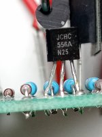
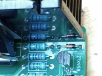
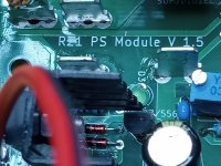
Did you take in the account that BC transistors, replacing ZTX parts, have different pin orientation if looking at their package. They should be mounted against silkscreen markings as rotated 180 degrees or backward. Look at post #103.
If that is done OK, then post some close-up pictures for both PCB sides.
If that is done OK, then post some close-up pictures for both PCB sides.
May be a repeated question.
Is R21 suitable as a regulated supply for high powered Class AB amplifiers?
Thanks
Is R21 suitable as a regulated supply for high powered Class AB amplifiers?
Thanks
1st post - 10 to 65VDC at up to 10 amps output.
So, if your AB amp has higher voltage rails - then no.
So, if your AB amp has higher voltage rails - then no.
Mine is not finished yet, but others are working in Tombo's class A amp, look for Vunce's posts. Tombo I am sure could offer more comment.
Due to critical parts unavailable for a long time, AFAIK there are only three amplifiers having that regulators, so far. Two mine and one Vunces’s.Any comment for listening experience?
Mine comments doesn’t count much because, as an author, I could be biased. It is up to other members to give the verdict.
From the technical standpoint, those regulators are close to ideal voltage sources for any audio amplifier. My experience is that they improve sound.
All amplifier designs with low PSRR (in example all DIY First Watt M2 amplifier variants and alike) would greatly benefit. However, there are no compelling reasons to use such regulators on class AB designs with very high PSRR like Wolverine in example.
Hello Tombo
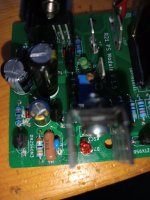
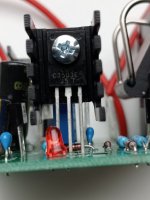
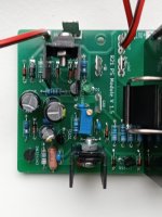
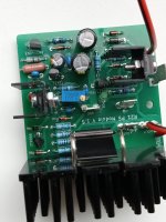
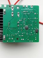
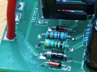
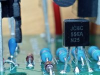
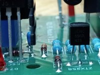
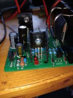
I checked the BC556, even desoldered it and tested it. Seems ok, so I hope you can help based on these photo's...
I built 3 positive R21 in parallel, part by part. I tested the second one and it works fine. As I tried to take care in putting them together I am surprised at my inconsistency to put it mildly.
But also very happy that I have one working that I will try with my Pass F1 this week.
Tomorrow I will hook up the third one and see whether that one works ok as well.
And thanks for any help or direction you could give me with solving this.
Attachments
-
 IMG20240218112709.jpg346.6 KB · Views: 142
 -
 IMG20240218123410.jpg295.7 KB · Views: 145
 -
 IMG20240218123340.jpg319.3 KB · Views: 149
 -
 IMG20240218123304.jpg309.7 KB · Views: 159
 -
 IMG20240218123258.jpg341.8 KB · Views: 160
 -
 IMG20240218123234.jpg279.7 KB · Views: 155
 -
 IMG20240218113142.jpg287.1 KB · Views: 150
 -
 IMG20240218113123.jpg361.2 KB · Views: 132
 -
 IMG20240218113029.jpg346.7 KB · Views: 128
 -
 IMG20240218113009.jpg281.1 KB · Views: 129
 -
 IMG20240218112949.jpg317.8 KB · Views: 129
 -
 IMG20240218112750.jpg416.1 KB · Views: 140
 -
 IMG20240218112720.jpg344.6 KB · Views: 146
It’s very good that one regulator works as expected. You can compare if there is any difference in part values or orientation. For the moment, I see suspicious colors on R1. Looks like 4.7 M resistor instead of 1000 x less required. Does green LED light on?

- Home
- Amplifiers
- Power Supplies
- An arguably better replacement for the resistor in a CRC power supply - R21 PS module